Air sampler with parallel impactors

a sampler and impactor technology, applied in the field of air samplers with parallel impactors, can solve the problems of heavy weight and complicatedness of samplers including pumps and batteries, and achieve the effect of improving sample quality and reducing the cost of passive sampling

Active Publication Date: 2006-07-11
SKC INC
View PDF25 Cites 23 Cited by
  • Summary
  • Abstract
  • Description
  • Claims
  • Application Information

AI Technical Summary

Problems solved by technology

Samplers including a pump and a battery for it tend to be heavier and more complicated than a passive sampler.

Method used


Image

  • Air sampler with parallel impactors
  • Air sampler with parallel impactors
  • Air sampler with parallel impactors

Examples


example 1

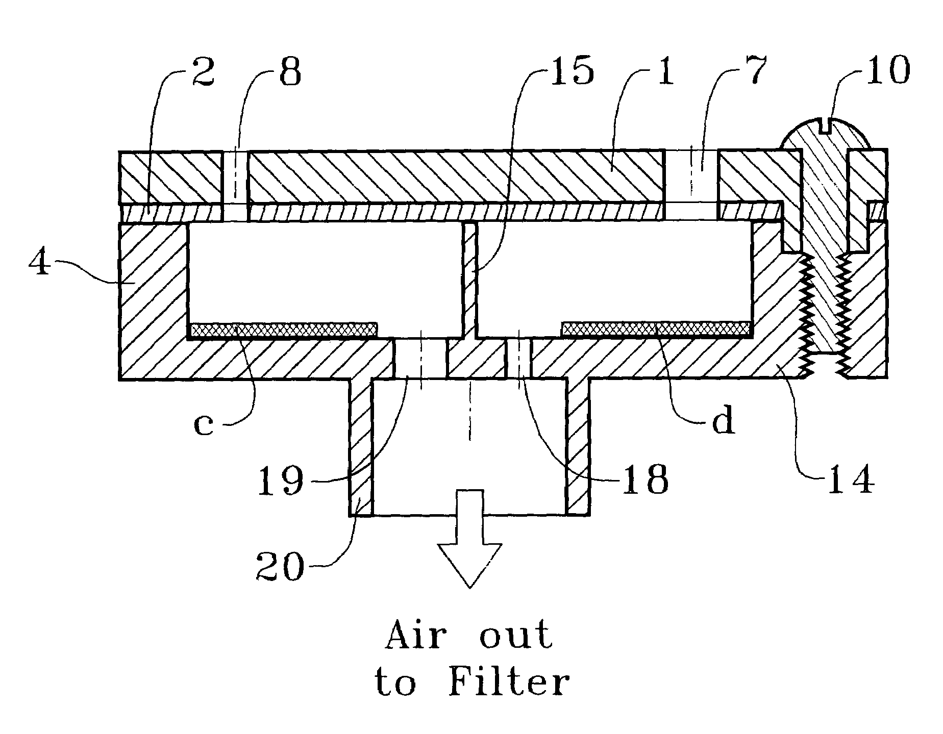
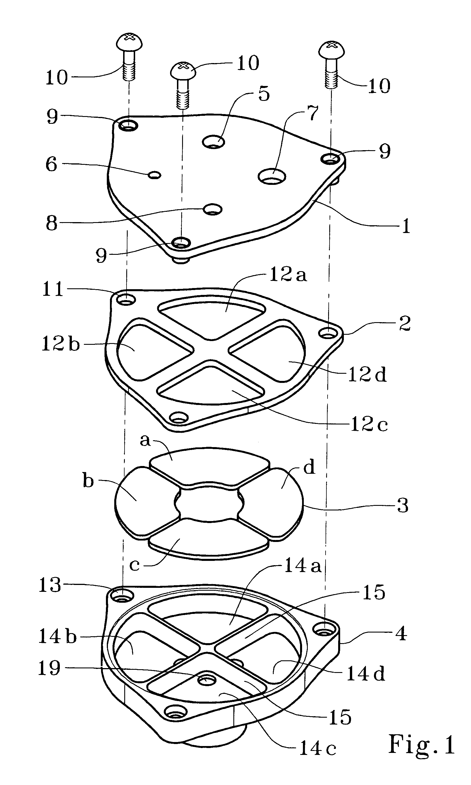
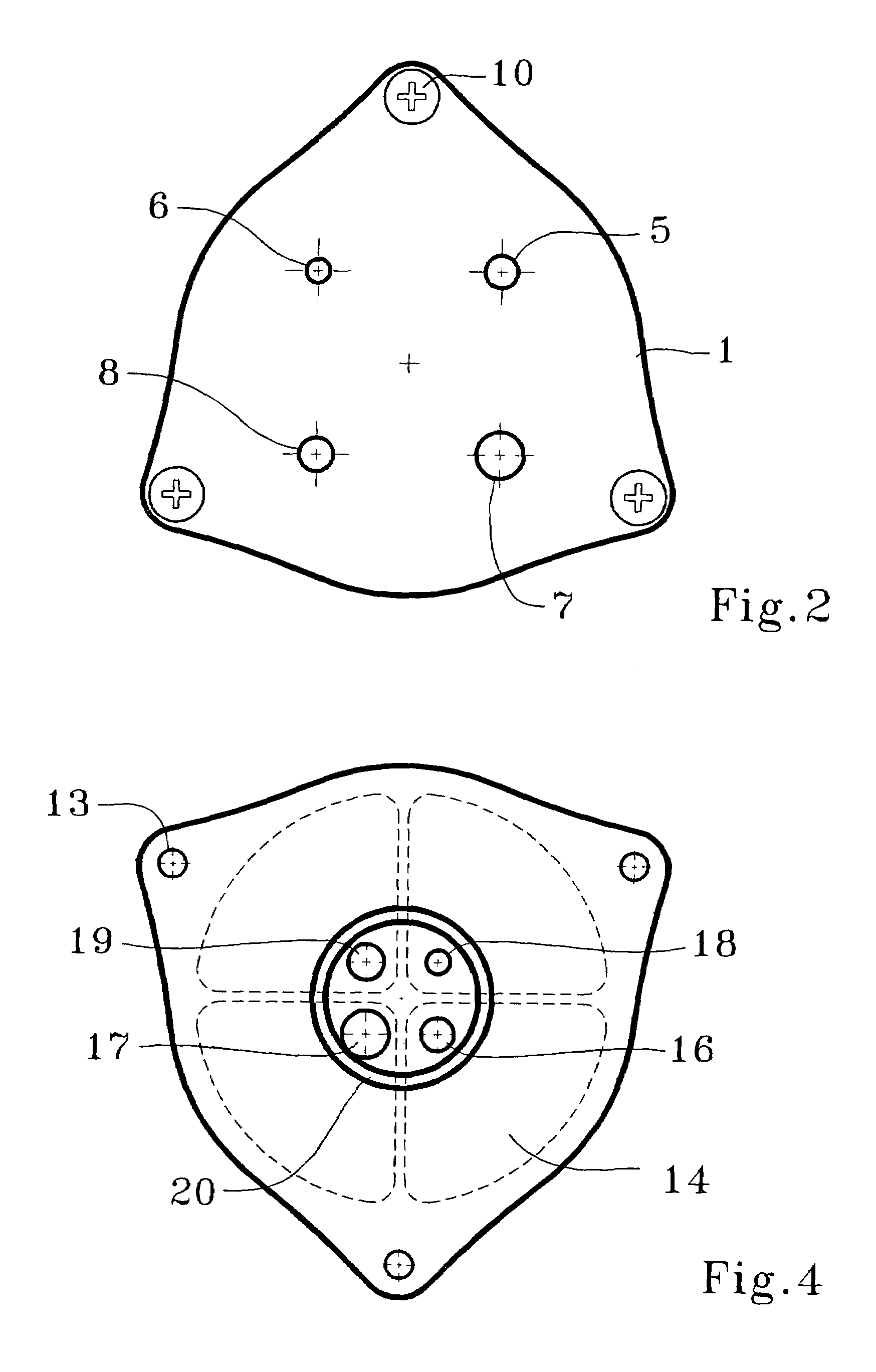
[0041]A sampler containing four parallel round-nozzle impactors and designed to approximate a respirable convention at 4.0 L / min (Table 1.) was machined and tested. The sampler incorporated a design similar to FIGS. 1–4 and the specifications of the 4-impactor design in Table 1 (Sampler 2). Experimental data are presented in FIGS. 5 and 6. Sampling efficiency was obtained by measuring particle concentration upstream and downstream of the sampler using an Aaerodynamic Particle Sizer (APS, Model 3320, TSI Inc., St. Paul, Minn.). FIG. 5 shows sampling efficiency of each separate impactor tested at 1.0 L / min (¼ of total flow). The dashed curve in FIG. 5 represents the respirable convention—the curve the sampler was designed to approximate. Table 1 shows that predicted d50 for impactors 1–4 at QS=1.0 L / min is 2.2, 3.5, 4.6 and 6.6 μm. Experimentally obtained 50% cut-off sizes were 2.7, 3.8, 4.7, and 6.0 μm accordingly (FIG. 6). As can be seen the experimental data is in good agreement wi...


PUM

PropertyMeasurementUnit
flow rateaaaaaaaaaa
sampling flow rateaaaaaaaaaa
flow rateaaaaaaaaaa

Abstract

An air sampler is designed for a predetermined flow rate. The air flow is admitted to at least two impactors operating in parallel. Preferably the inlet nozzles and the outlet orifices of each impactor are sized to achieve predetermined cut-off sizes of particles; preferably the composite curve of all the impactors will mimic a predetermined particle sampling efficiency curve.

Description

TECHNICAL FIELD[0001]An air sampler divides incoming air into a plurality of parallel flows to separate collectors or collection chambers (sometimes known as impactors). A portion of the particles striking the separate impactors is retained and a portion of the particles in the sampled air continues through outlet orifices in the impactors for optional retention on a filter or other repository. While equal pressure drops are maintained across all collectors, the nozzles or orifices leading to each of the impactors have different effective areas in order to provide predetermined size-selective collection efficiencies at a selected overall air flow rate.BACKGROUND OF THE INVENTION[0002]Personal air samplers are designed to be worn by industrial workers and others who have reason for concern about particles, aerosols, microorganisms, fibers, and other small materials in the atmosphere they breathe. Since the air samplers are normally worn on the clothing of the user, they should be lig...

Claims


Application Information

Patent Timeline
Patent Type & Authority Patents(United States)
IPC IPC(8): G01N1/24G01N1/40G01N1/22
CPCG01N1/2208
Inventor TRAKUMAS, SAULIUSHALL, PETER M.
Owner SKC INC
Why Eureka
Try Eureka