
Apparatus and method of converting frame and/or field rate using adaptive motion compensation

a technology of adaptive motion compensation and image signal, which is applied in the field of apparatus and method of converting the format of image signal, can solve the problems of blurring at the edges of images, visual annoying motion jitter, and block artifacts, and achieve the effect of reducing frame/field block artifacts

Inactive Publication Date: 2006-07-11
SAMSUNG ELECTRONICS CO LTD
View PDF14 Cites 18 Cited by
  • Summary
  • Abstract
  • Description
  • Claims
  • Application Information

AI Technical Summary

Benefits of technology

The present invention provides a method and apparatus for converting the frame and field rate of an image signal to reduce block artifacts caused by motion information. The method involves estimating the motion vector of a frame and field to be interpolated, analyzing the motion vector to determine motion information, and generating pixels to be interpolated using motion compensation and spatiotemporal interpolation based on the motion information and correlation between neighboring blocks. The technical effect of this invention is to improve the quality of image signals and reduce the impact of motion on image quality.

Problems solved by technology

In the early stage of TV format conversion, the format conversion was performed using a repetition of a frame and a simple spatiotemporal filter, which caused visually annoying motion jitter and blurring at the edges of an image.
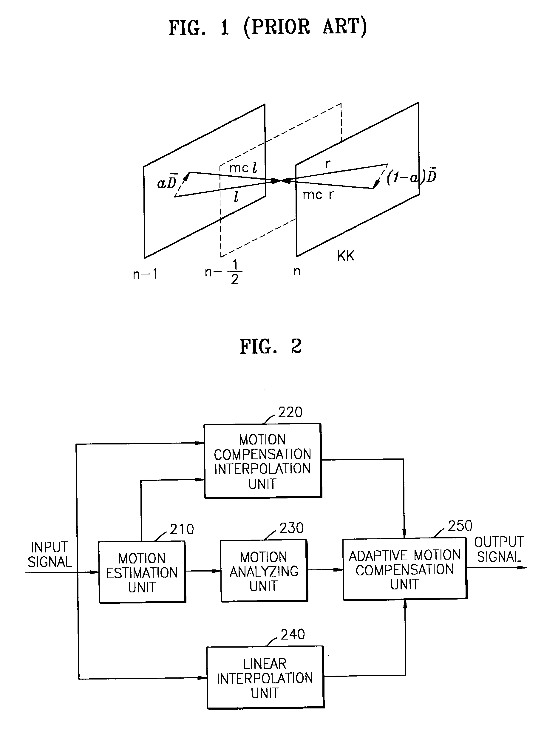
Since the conventional compensation-type interpolation method is performed in units of a frame / field block, if the estimated motion vector {right arrow over (D)} is not accurate, block artifacts occur.

Method used


Image

  • Apparatus and method of converting frame and/or field rate using adaptive motion compensation
  • Apparatus and method of converting frame and/or field rate using adaptive motion compensation
  • Apparatus and method of converting frame and/or field rate using adaptive motion compensation

Examples


Embodiment Construction

[0024]Reference will now be made in detail to the present embodiments of the present invention, examples of which are illustrated in the accompanying drawings, wherein like reference numerals refer to the like elements throughout. The embodiments are described below in order to explain the present invention by referring to the figures.

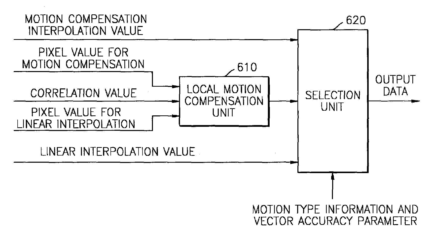
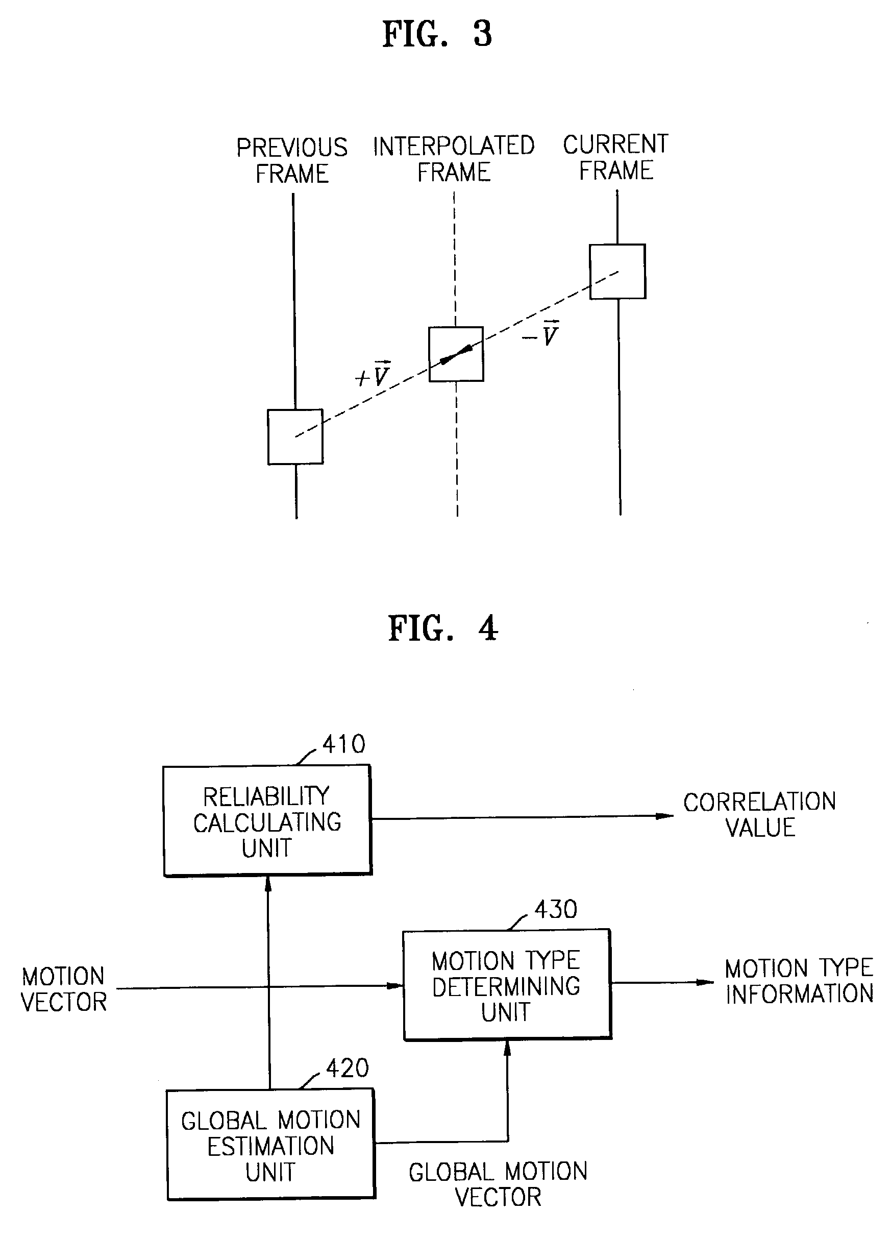
[0025]The apparatus for converting a frame rate using adaptive motion compensation according to the embodiment of the present invention shown in FIG. 2 has a motion estimation unit 210, a motion analyzing unit 230, a motion compensation interpolation unit 220, a linear interpolation unit 240, and an adaptive motion compensation unit 250. The motion estimation unit 210 estimates a motion vector of a frame / field to be interpolated and the accuracy of the motion vector using motion vectors between previous and next frames / fields. That is, block-based motion estimation is performed between two frames / fields that are continuously input. A current frame / fiel...


PUM


Abstract

An apparatus and method which includes estimating a motion vector of a frame and / or field to be interpolated and the accuracy of the motion vector using motion vectors of previous and next frames and / or fields; determining motion information by analyzing the estimated motion vector, and calculating a correlation between the motion vector of the current block and the motion vectors of neighboring blocks; generating pixels to be interpolated by performing motion compensation in a frame and / or field to be interpolated using the estimated motion vector and using pixels neighboring a pixel to be interpolated in the frame and / or field to be interpolated and pixels neighboring a pixel to be interpolated in the previous and next frame and / or field of the pixel to be interpolated; and outputting the generated pixels as interpolation values according to the accuracy of the estimated motion vector, the motion information, and the correlation.

Description

CROSS-REFERENCE TO RELATED APPLICATION[0001]This application claims the benefit of Korean Application No. 2001-66014, filed Oct. 25, 2001 in the Korean Intellectual Property Office, the disclosure of which is incorporated herein by reference.BACKGROUND OF THE INVENTION[0002]1. Field of the Invention[0003]The present invention relates to an apparatus and method of converting the format of an image signal, and more particularly, to an apparatus and method of converting a frame and / or field rate using different motion compensation methods according to motion information of each block of the frame / field.[0004]2. Description of the Related Art[0005]In general, in order to exchange TV programs complying with a variety of TV standards, a format conversion of the programs is needed. In the early stage of TV format conversion, the format conversion was performed using a repetition of a frame and a simple spatiotemporal filter, which caused visually annoying motion jitter and blurring at the ...

Claims


Application Information

Patent Timeline
Patent Type & Authority Patents(United States)
IPC IPC(8): H04N7/12G06K9/36G06K9/00H04N5/14H04N7/01
CPCH04N5/145H04N7/014H04N7/0137H04N7/01
Inventor LEE, SUNG-HEEYANG, SEUNG-JOON
Owner SAMSUNG ELECTRONICS CO LTD
Learn More