Seat for vehicle

a seat and vehicle technology, applied in the field of seats for vehicles, can solve problems such as poor sitting comfort, and achieve the effects of preventing or minimizing uncomfortable lateral oscillation of the occupant's body, reducing the lateral movement of the cushioning receiving member, and improving the sitting comfort of the occupan

Inactive Publication Date: 2006-07-18
HONDA MOTOR CO LTD
View PDF5 Cites 19 Cited by
  • Summary
  • Abstract
  • Description
  • Claims
  • Application Information

AI Technical Summary

Benefits of technology

[0007]The present invention is directed toward a seat for a vehicle that prevents or minimizes uncomfortable lateral oscillation of an occupant's body. The present invention is further directed toward a vehicle seat that improves sitting comfort of the occupant by permitting longitudinal and vertical movement of a cushion receiving member for supporting the cushion member of the seat and restricting lateral movement of the cushion receiving member.
[0009]With the above arrangement, the first cushion receiving member of the seat cushion and the second cushion receiving member of the seat back are turnably connected to each other; the first cushion receiving member is turnably supported at its front end at the front end of the first framework; and the second cushion receiving member is supported on the second framework through the spring, which is fixed at its upper portion at at least two points to the second framework and is also fixed at its lower portion to the second framework. Therefore, the first and second cushion receiving members can be moved vertically and longitudinally, while being prevented from being oscillated laterally, leading to an improvement in feeling of stability of sitting comfort.
[0011]With the above arrangement, vibration caused by the expansion and contraction of the spring is dampened by the elastic fabric, and thereby decreases fatigue experienced by the occupant.
[0013]With the above arrangement, at least a portion of the first framework of the seat cushion is formed by coupling the pipe materials, and at least a portion of an operating cable connecting the manipulating member mounted on the first framework to the seat-mounting device is accommodated in the pipe materials. Therefore, the cable can be hidden invisibly to improve aesthetic appearance, and can be prevented from being damaged by contact with other members.
[0015]With the above arrangement, the operating cable is reeved around the coupled portion of the pipe materials of the first framework coupled at the blunt angle. Therefore, steep or sharp bending of the operating cable is avoided, and the seat-mounting device can be smoothly operated.
[0017]With the above arrangement, the manipulating member is disposed at the end of the laterally-extending pipe material at the front portion of the first framework to support the front end of the first cushion receiving member. Therefore, the occupant sitting on the seat can easily manipulate the manipulating member.

Problems solved by technology

The seat described in Japanese Patent Application Laid-open No. 2002-78561 suffers from a problem that a body of an occupant sitting on the seat may be oscillated laterally and, hence, the attitude of the occupant is not stabilized, resulting in a poor sitting comfort, because the first cushion receiving member on the side of a seat cushion and the second cushion receiving member on the side of a seat back are supported in the floating manner in the first and second frameworks with the resilient members or springs interposed therebetween.

Method used


Image

  • Seat for vehicle
  • Seat for vehicle
  • Seat for vehicle

Examples


Embodiment Construction

[0030]The present invention will now be described by way of an embodiment with reference to the accompanying drawings.

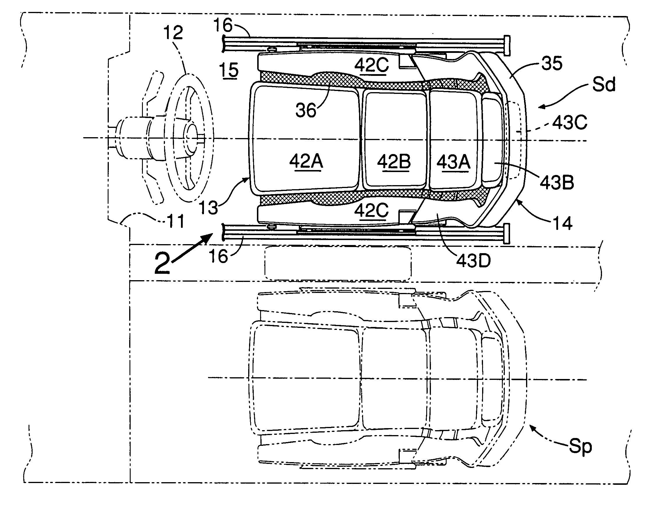
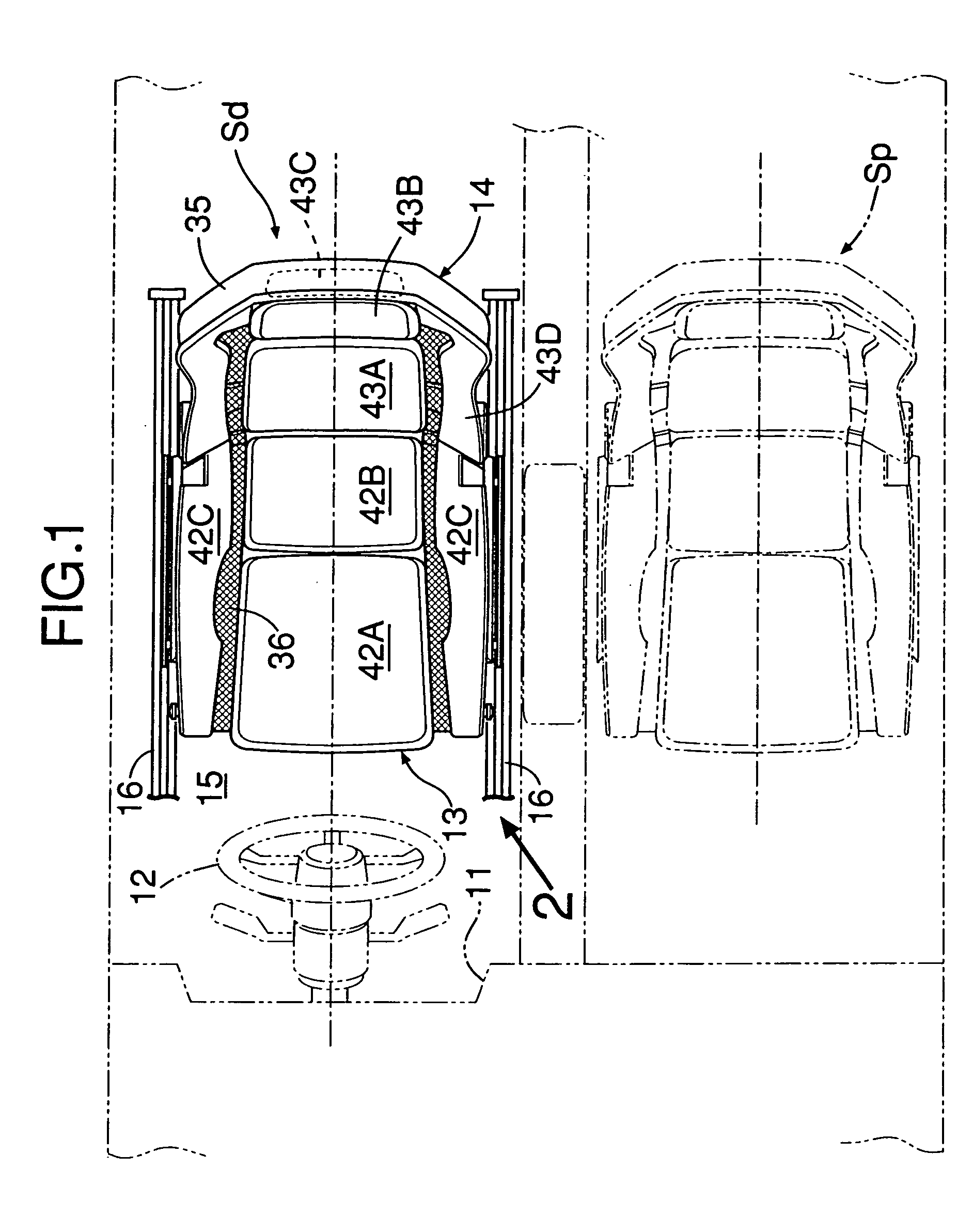
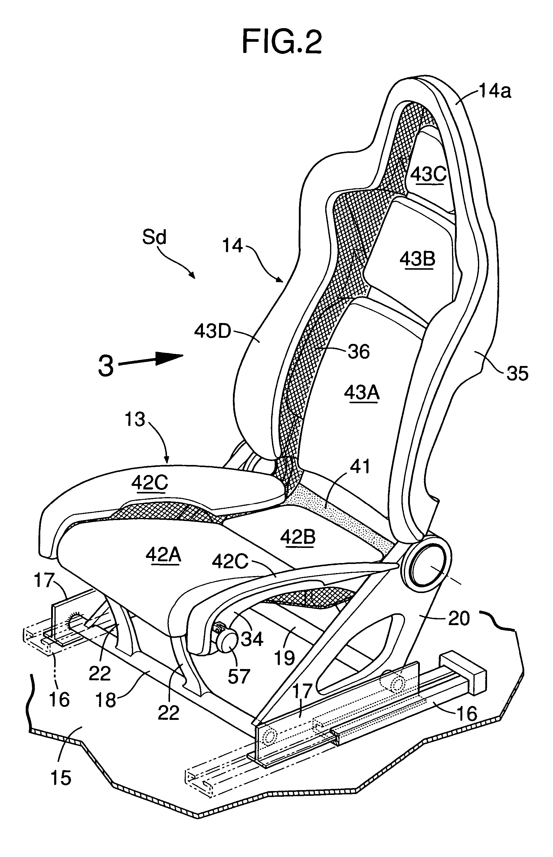
[0031]As shown in FIGS. 1 to 5, a front seat arrangement for an automobile comprises: a driver's seat Sd located behind a steering wheel 12 mounted on the right of a dashboard 11; and a passenger's seat Sp juxtaposed on the left of the driver's seat Sd. The driver's seat Sd includes: a seat cushion 13 disposed generally horizontally to support a driver's buttocks and a seat back 14 which recliningly rises from a rear end of the seat cushion 13. A head rest 14a is integrally formed at an upper end of the seat back 14. Left and right sliders 17, 17 are slidably fitted to left and right guide rails 16, 16 extending longitudinally on a floor panel 15. The left and right sliders 17, 17 are connected to each other by a front connecting member 18 and a rear connecting member 19. Each of the connecting members 18, 19 is made from a pipe material. A pair of left and right bas...


PUM


Abstract

A first cushion receiving member of a seat cushion and a second cushion receiving member of a seat back are turnably connected to each other by a connecting member. The first cushion receiving member is turnably supported at its front end on a front frame of a first framework. The second cushion receiving member is supported on a second framework, through a spring fixed at its upper portion at at least two points and at its lower portion to the second framework and through an elastic fabric having a periphery fixed to the second framework. Thus, the first and second cushion receiving members can be prevented from being oscillated laterally, and the vibration caused by the expansion and contraction of the spring can be dampened by the elastic fabric. As a result, it is possible to permit the longitudinal and vertical movement of the first and second cushion receiving members for supporting the cushion members of the seat and to restrict the lateral movement of the cushion receiving members, and to thereby prevent uncomfortable lateral oscillation of an occupant's body so as to improve sitting comfort.

Description

RELATED APPLICATION DATA[0001]Japanese priority application Nos. 2004-162155 and 2004-162156, upon which the present application is based, are hereby incorporated in their entirety herein by reference.BACKGROUND OF THE INVENTION[0002]1. Field of the Invention[0003]The present invention relates to a seat for a vehicle, comprising a seat cushion disposed generally horizontally for supporting an occupant's buttocks, and a seat back rising from a rear portion of the seat cushion for supporting the occupant's back, the seat cushion supporting a first cushion member on a first framework with a first cushion receiving member interposed therebetween, the seat back supporting a second cushion member on a second framework with a second cushion receiving member interposed therebetween.[0004]2. Description of the Related Art[0005]Such a seat for a vehicle is known, for example, from Japanese Patent Application Laid-open No. 2002-78561. This seat for the vehicle has a structure in which a first ...

Claims


Application Information

Patent Timeline
Patent Type & Authority Patents(United States)
IPC IPC(8): A47C7/02A47C7/14A47C7/00B60N2/68B60N2/70
CPCB60N2/68B60N2/682B60N2/70B60N2/7011
Inventor NAKAMURA, MITSUMASA
Owner HONDA MOTOR CO LTD
Why Eureka
Try Eureka