
Welding connector

a technology of connectors and wires, applied in the direction of coupling contact members, coupling device connections, electrical apparatus, etc., can solve the problems of connectors being unscrewed from one another, the connection system is relatively more prone to inadvertent disengagemen

Inactive Publication Date: 2006-07-18
DUAL MACHINE PROD
View PDF6 Cites 31 Cited by
  • Summary
  • Abstract
  • Description
  • Claims
  • Application Information

AI Technical Summary

Problems solved by technology

However, it suffers in that, over time, the various surfaces in the connectors can wear, thereby to reduce frictional engagement and render the connector system relatively more prone to inadvertent disengagement.
This problem is most evident when the cables are strung in series up a scaffolding or the like, since the weight of the cables can cause the connectors to unscrew from one another and release, particularly when the junction between the connectors has become loose through wear.

Method used


Image

  • Welding connector
  • Welding connector
  • Welding connector

Examples


Embodiment Construction

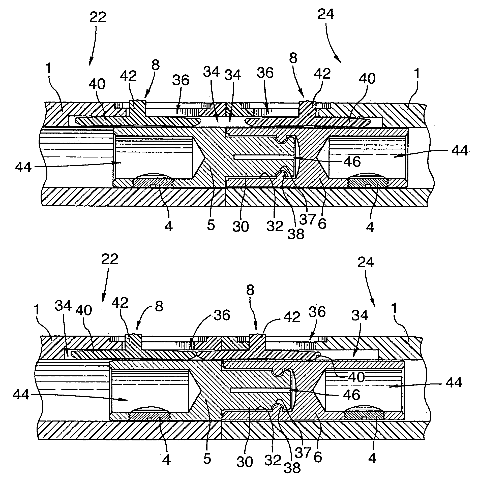
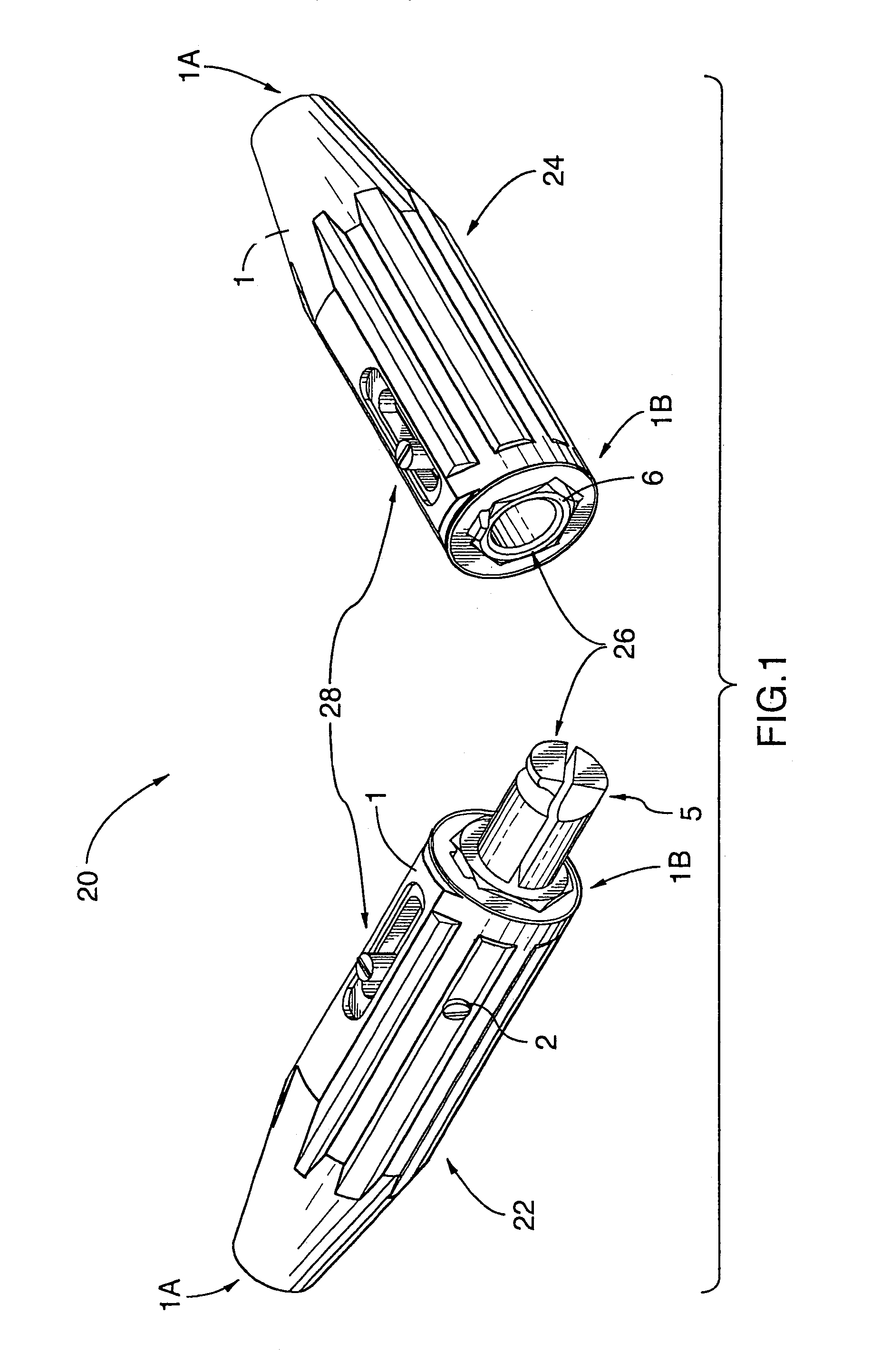
[0017]FIG. 1 shows a welding connector assembly 20 according to a preferred embodiment of the present invention. The welding connector assembly 20 is for joining two welding cables (not shown in FIG. 1) and comprises a pair of welding connectors 22,24, the pair including a first connector 22 and a second connector 24. Each welding connector 22,24 includes a body 5,6 and a tubular sleeve 1,1, and the pair of welding connectors 22,24 includes a primary lock 26 and a secondary lock 28.

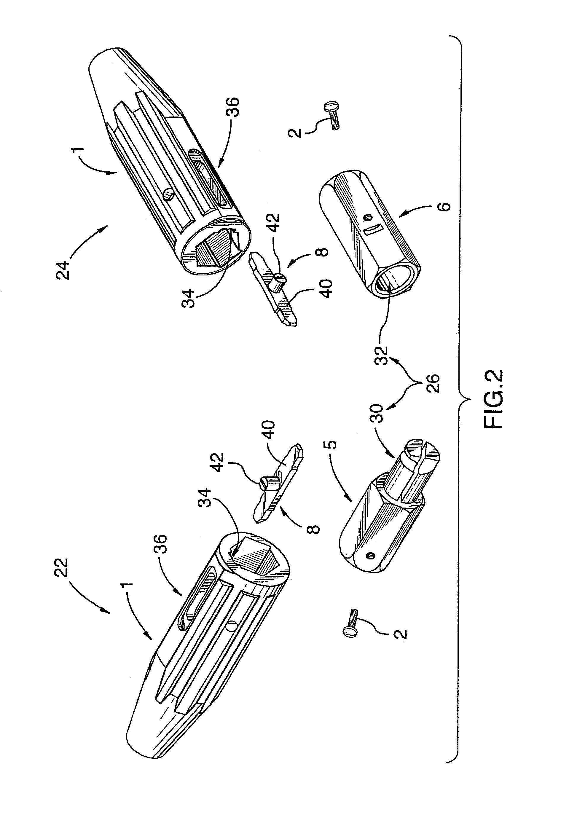
[0018]FIG. 2 shows the welding connectors 22,24 dissembled, to provide a view of, inter alia, the bodies 5,6 and sleeves 1,1.

[0019]Each body 5,6 is constructed from electrically-conductive material, specifically brass, although other materials can be used.

[0020]FIG. 3 is a view similar to FIG. 2, but also showing cables 7,7 with exposed ends threaded through the sleeves 1,1 and the bodies 5,6 disassembled. Each body 5,6 includes receiving means for securely releasably receiving in electrically-conducting ...


PUM


Abstract

An assembly is disclosed and comprises a pair of connectors, each including a body which securely receives in electrically-conducting relation the end of a welding cable and a sleeve which, in use, forms a grip for the body and receives same in a manner which provides access to the receiver for the cable end at one end and provides access to the body at the other end. The pair has: an initial position wherein they define a longitudinal axis and wherein the sleeves are disposed other end-to-other end, aligned with the axis; a primary lock, which locks the connectors against longitudinal movement relative to one another upon rotation of the connectors relative to one another about the axis from the initial position and permits electrical conduction between the bodies when the connectors are so locked; and a secondary lock which selectively arrests relative rotation of the connectors about the axis.

Description

[0001]This application claims benefit of the filing date of and right of priority of U.S. Provisional Patent Application Ser. No. 60 / 526,529 filed Dec. 3, 2003 under 35 USC §119(e).FIELD OF THE INVENTION[0002]This invention relates generally to welding equipment, and more particularly, relates to welding cable connectors, that is, connectors for use with welding cable.BACKGROUND OF THE INVENTION[0003]It is well known in the prior art to provide connector systems for welding cable.[0004]One common form of connector system is of the general type described in U.S. Pat. No. 4,702,539 (Cusick III, et al.), issued Oct. 27, 1987. In this type of connector system, a pair of connectors, said pair comprising a male connector and a female connector, is provided. Each connector includes a body and a sleeve. The body is constructed from electrically-conductive material, such as brass, and includes receiver means for securely receiving in electrically-conducting relation the end of a welding cabl...

Claims


Application Information

Patent Timeline
Patent Type & Authority Patents(United States)
IPC IPC(8): H01R4/50H01R3/00H01R4/00H01R13/213
CPCH01R13/213H01R4/54
Inventor BEHOO, RONALD JAMES
Owner DUAL MACHINE PROD
Learn More