Dual switch for selective removal of recording medium from compound device

a technology of electric switch and compound device, which is applied in the direction of contact mechanism, record information storage, instruments, etc., can solve the problems of increasing assembly work, compound device less attractive appearance, and increasing manufacturing cos

Inactive Publication Date: 2006-08-22
ORION ELECTRIC CO LTD
View PDF11 Cites 28 Cited by
  • Summary
  • Abstract
  • Description
  • Claims
  • Application Information

AI Technical Summary

Benefits of technology

[0010]In a compound device combining two pieces of equipment such as a disk device and a video device having a slot with respect to each equipment on its front panel to take a recording medium such as a video cassette or a disk out of the respective slot, a dual switch comprising two switching means on a base plate and a button capable of selectively actuating either switching means to take a recording medium out of the slot is improved according to the present invention in that the button has resilient means responsive to removal of pressure from the button for returning to its original position.

Problems solved by technology

Arrangement of two switches on the front panel makes the compound device less attractive in appearance.
Also, use of two switches disadvantageously increases the assembly work and accordingly the manufacturing cost of the compound device increases.
The front panel with two rectangular holes requires a metal mold whose shape is rather complicated, and accordingly the metal mold costs much.
The resilient pieces are small compared with the front panel, and therefore, it is very difficult to make them into exact shape and size as required when the front panel having the cantilever-like pieces appearing halfway in its apertures is injection-molded.
It is almost impossible to make a front panel whose cantilever-like pieces are of a material (or spring metal) which is different from that of the front panel.
As a matter of fact it is practically impossible to injection-mold a front panel whose cantilever-like pieces extend halfway in its apertures.

Method used


Image

  • Dual switch for selective removal of recording medium from compound device
  • Dual switch for selective removal of recording medium from compound device
  • Dual switch for selective removal of recording medium from compound device

Examples


Embodiment Construction

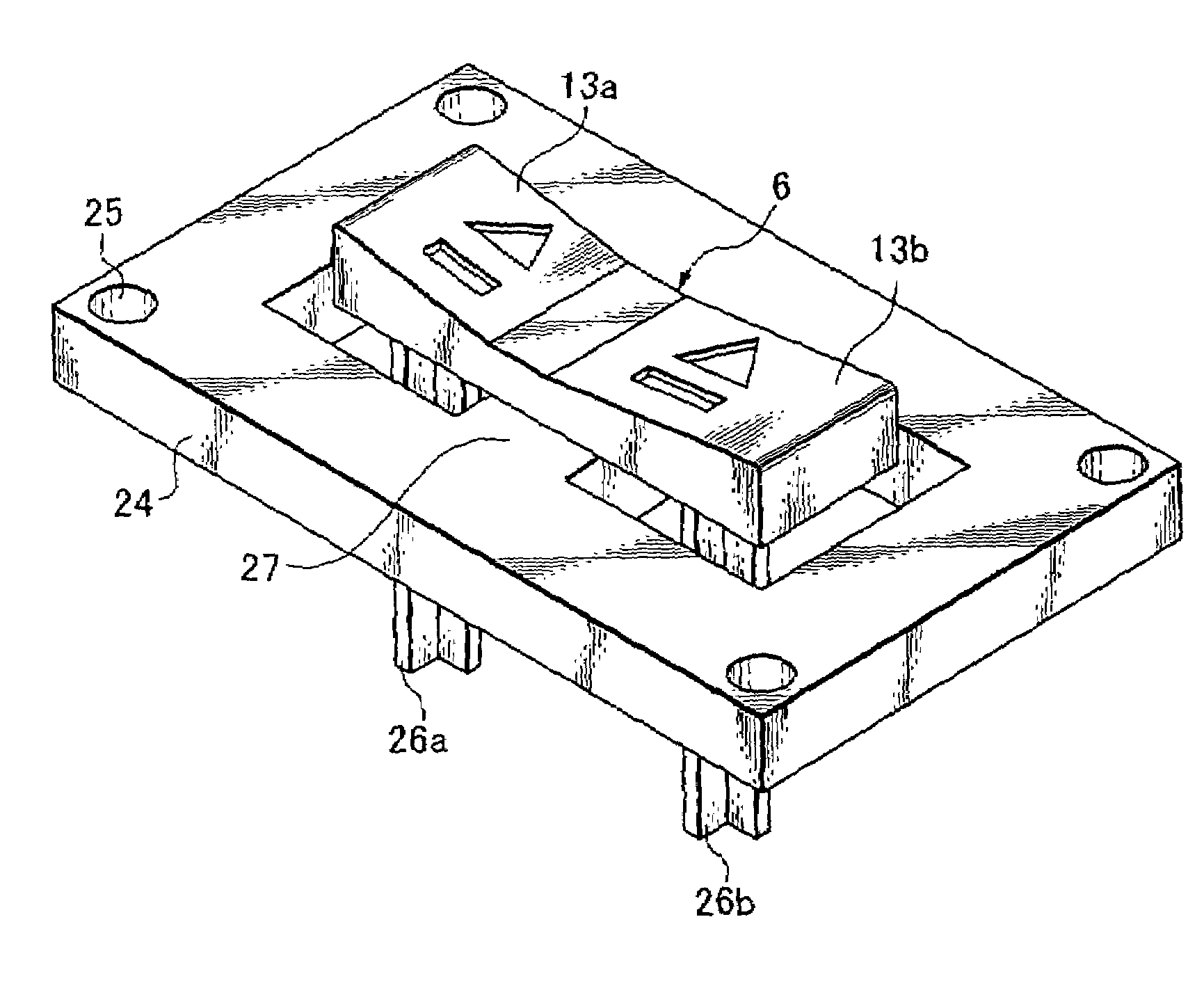
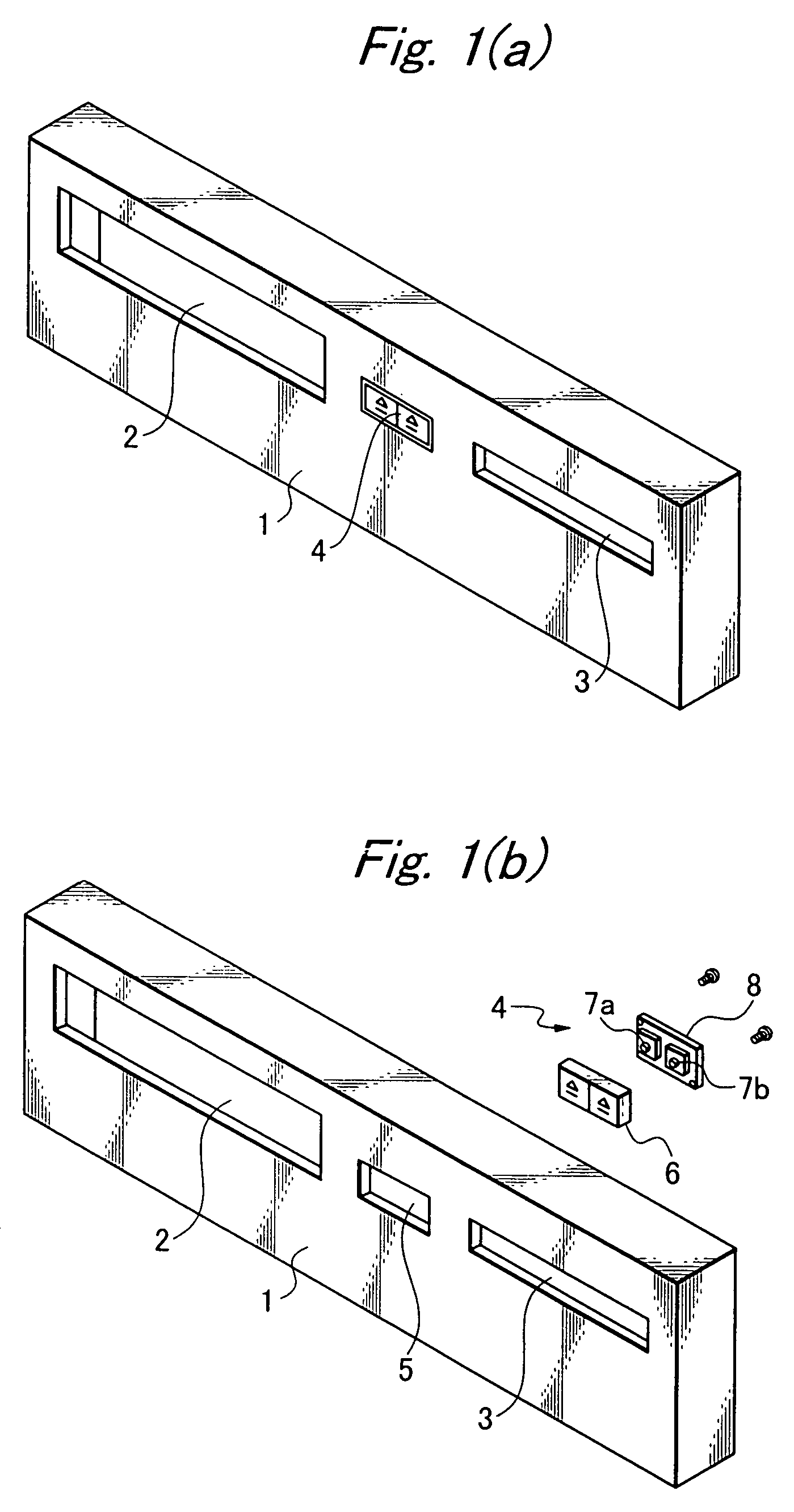
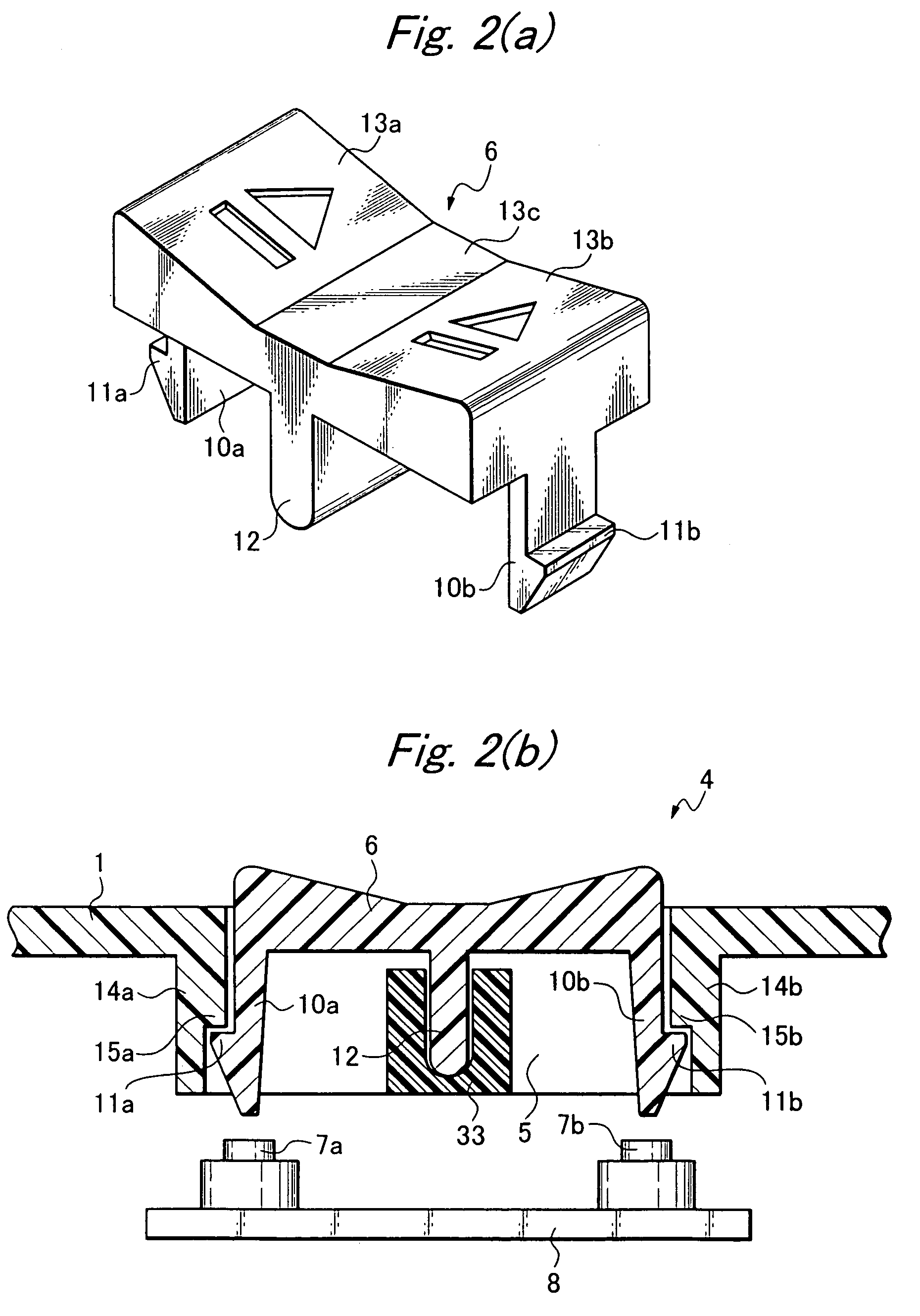
[0024]Referring to FIG. 1a, a compound device has a cassette slot 2 and a disk slot 3 formed on its front panel 1. A dual switch 4 according to the present invention is between the cassette slot 2 and the disk slot 3. FIG. 1b shows the dual switch 4 in an exploded state. Its button 6 is a seesaw type to be fitted in the rectangular aperture 5 made between the cassette slot 2 and the disk slot 3 in the panel 1. As shown, two switching means or switches 7a and 7b are on a base plate 8. When the seesaw button 6 is depressed on the right side by a finger, the right switching means 7b turns on, and then a disk tray bearing a disk appears from the disk slot 3. When the seesaw button 6 is depressed on the left side by finger, the left switching means 7a turns on, and then the videotape or cassette appears from the cassette slot 2. When the pressure by finger is removed from the seesaw button 6, the button returns to its original horizontal position.

[0025]One example of such a seesaw button...


PUM

PropertyMeasurementUnit
pressureaaaaaaaaaa
lengthaaaaaaaaaa
shapeaaaaaaaaaa

Abstract

A dual switch for selective removal of a recording medium from a compound device is so exactly sized and shaped that are exact switching action may be assured. Two switches are on a base plate, and a button is capable of selectively actuating either switch to take a recording medium out of the slot. The button has resilient member responsive to removal of pressure from the button for returning to its original position. The button can be of seesaw, slide or rotary type.

Description

BACKGROUND OF THE INVENTION[0001]1. Field of the Invention[0002]The present invention relates to an electric switch for selective removal of a recording medium from a compound device which combines two pieces of equipment, such as a disk device and video device.[0003]2. Related Art[0004]Referring to FIG. 7, a compound device combines a video device and a disk device, and it has a cassette slot 51 and a disk slot 52 formed in its front panel 50. Also, the front panel 50 has a button switch 53 on the left side of the cassette slot 51, and another button switch 54 on the right side of the disk slot 52. Depression of the button switch 53 causes the cassette to appear from the cassette slot 51 whereas depression of the button switch 54 causes a disk tray to appear from the disk slot 54. When the compound device is loaded with a new cassette, the cassette is pushed in the cassette slot 51. When the compound device is loaded with a new disk, the disk is put on the tray, which appears from ...

Claims


Application Information

Patent Timeline
Patent Type & Authority Patents(United States)
IPC IPC(8): H01H23/24H01H15/10G11B15/10G11B19/02G11B19/18G11B25/10H01H15/06H01H19/14H01H23/14H01H23/30
CPCG11B15/106G11B19/022G11B19/18G11B25/10H01H19/14H01H23/14H01H15/06H01H2221/044H01H15/107H01H23/145
Inventor TSUNEMOTO, KINICHI
Owner ORION ELECTRIC CO LTD
Why Eureka
Try Eureka