Methods for capturing fingerprint images using a moving platen

a technology of moving plates and fingerprint images, applied in the field of security control, can solve the problems of inability to capture fingerprint images, severe limitations of the system, and use of ink, and achieve the effect of reducing the cost of the motor

Inactive Publication Date: 2006-09-05
CROSS MATCH TECH
View PDF197 Cites 21 Cited by
  • Summary
  • Abstract
  • Description
  • Claims
  • Application Information

AI Technical Summary

Benefits of technology

[0010]By utilizing the bar code as a caliper, it is now possible to accurately and repeatably record and store high resolution optical images of fingerprints with no apparent loss of accuracy owing to the electronic knitting process. The caliper enables the microprocessing device to positively identify and organize each of the individual slices which make up the final image. It then becomes possible for an individual to rotate their fingertip in a back and forth motion, without concern for rotation speed, until such time as the device acquires accurate data for all of the required slices. The microprocessing device is then able to reassemble the recorded data by matching said data to the particular segments delineated by the fixed caliper gradations, and knitting the appropriate slices together so as to form a complete image of the fingerprint with minimal loss of resolution.
[0011]Thus, it is an objective of the present invention to provide a method and apparatus whereby an untrained individual can accurately record electronic optical images of their fingerprints.
[0013]It is an additional objective of the invention to provide a method and apparatus whereby individual segments of data, having the attributes of portions of the image of a fingertip, may be accurately recorded in a random fashion and then reassembled so as to produce an accurate and coherent image of the original fingerprint.
[0015]Yet still another objective of the invention is to provide an apparatus that does not have a real time element allowing a user to roll as fast or as slow as they feel comfortable.
[0016]Another objective of the invention is to provide an apparatus whereby the individual drives the scanner mechanism, thereby eliminating the cost of a motor or the like drive mechanism for moving fingers over the scanner, or the scanner past the fingers.

Problems solved by technology

This system has severe limitations, the least of which is the use of ink which can often require several attempts before a usable image is obtained.
Furthermore, use of an ink-based system requires cooperation of the individual from whom the prints are being taken, since blurring and smearing of the prints often occurs when attempts are made to obtain fingerprints from a hostile individual.
Additionally, it is difficult to easily adapt inked prints for computerized storage and retrieval; thus making it difficult for various governmental agencies to reliably transfer and share data.
If the fingers are not rotated at the correct speed, data will be lost necessitating repeating of the entire procedure.
Several of these systems generate an optical image in real time, but they suffer from errors caused by their need to approximate the complete fingerprint image by electronically combining a plurality of smaller images or “slices” and smoothing the edges of the slices together to form an image which has the appearance of a full fingerprint.
Such images still engender a degree of inaccuracy which, when coupled with the limits of resolution and recording inherent in the available hardware, render them unacceptable.

Method used


Image

  • Methods for capturing fingerprint images using a moving platen
  • Methods for capturing fingerprint images using a moving platen
  • Methods for capturing fingerprint images using a moving platen

Examples


Embodiment Construction

)

[0032]Although the invention will be described in terms of a specific embodiment, it will be readily apparent to those skilled in this art that various modifications, rearrangements and substitutions can be made without departing from the spirit of the invention. The scope of the invention is defined by the claims appended hereto.

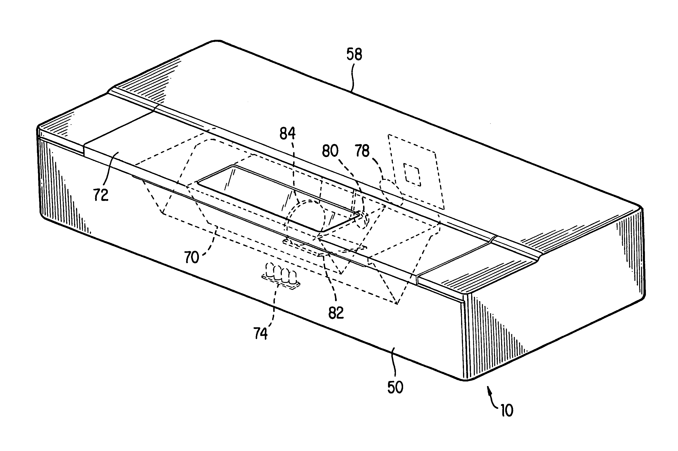
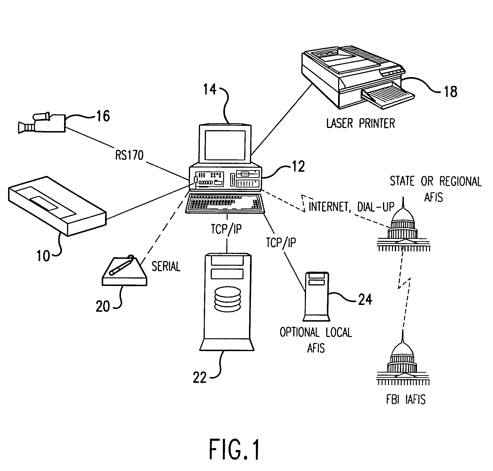
[0033]Referring now to FIG. 1, set forth is a pictorial of the invention and system comprising a scanner 10 coupled to a computer 12 having a PCI framegrabber board and monitor 14. The system may include a laser printer for local printout. An optional camera 16 may be used for identity verification. In addition, a signature tablet 20 provides another optional identity verification.

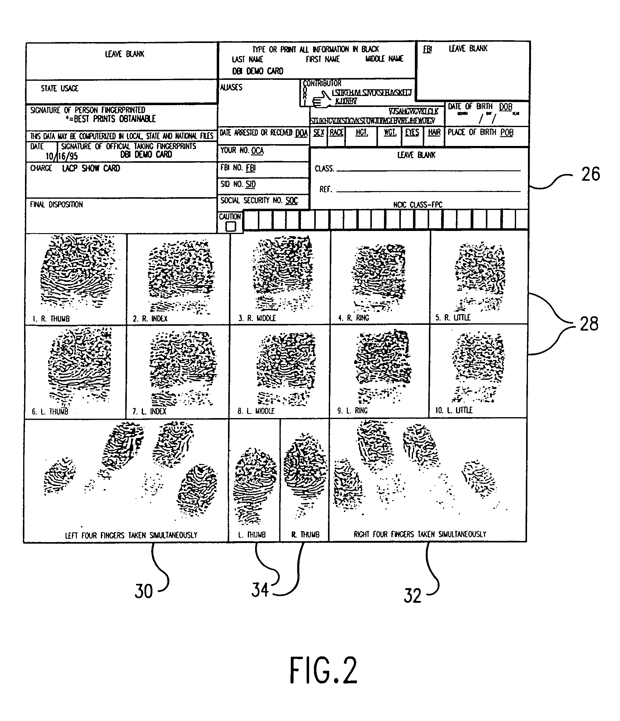
[0034]The scanner of the instant invention is developed primarily for use by criminal justice systems to collect images of all ten prints of an individual that have been rolled from fingernail to fingernail. The purpose of collecting the prints is to place them in a database 22 w...


PUM


Abstract

A method and apparatus whereby a fingerprint verifier has a mechanism to slide a prism over an imaged area of a camera. The position of the prism being determined by a binary absolute linear code on a sliding mechanism imaged by the same camera at the side of the fingerprint wherein the images are knitted together to simulate a large CCD.

Description

[0001]This application is a divisional application of U.S. patent application Ser. No. 09 / 759,344, filed Jan. 16, 2001, now issued as U.S. Pat. No. 6,628,813, which is a continuation of U.S. patent application Ser. No. 09 / 067,792, filed Apr. 28, 1998, now issued as U.S. Pat. No. 6,178,255.FIELD OF THE INVENTION[0002]The instant invention is directed to the field of security control and, in particular, to the electronic acquisition of optical fingerprint images and the accurate and repeatable storage thereof.BACKGROUND OF THE INVENTION[0003]Prior art techniques for obtaining fingerprints have included application of ink to a person's fingertips and rolling or simply pressing the tips of the individual's fingers to appropriate places on a recording card. This system has severe limitations, the least of which is the use of ink which can often require several attempts before a usable image is obtained. Furthermore, use of an ink-based system requires cooperation of the individual from w...

Claims


Application Information

Patent Timeline
Patent Type & Authority Patents(United States)
IPC IPC(8): G06K9/00
CPCG06K9/00026G06V40/1335
Inventor SCOTT, WALTER GUYFEDELE, DEAN J.
Owner CROSS MATCH TECH
Why Eureka
Try Eureka