Method for compensating secondary current of current transformers

a current transformer and secondary current technology, applied in resistance/reactance/impedence, digital variable display, instruments, etc., can solve the problems of unplanned maloperation delay in the operation time of the protective relay system, application of the conventional method, etc., to achieve the effect of reducing the difficulty of measuring and estimating the value of the remanent magnetic flux

Inactive Publication Date: 2006-09-05
HANKOOK IED
View PDF11 Cites 6 Cited by
  • Summary
  • Abstract
  • Description
  • Claims
  • Application Information

AI Technical Summary

Benefits of technology

[0007]Accordingly, the present invention has been made keeping in mind the above problems occurring in the prior art, and an object of the present invention is to provide a method for compensating the secondary currents of current transformers, which can obtain a precise secondary current value consistent with a current transformation ratio during the saturation of a current transformer even when there is no information on the value of an initial remanent magnetic flux, thus preventing the unwanted maloperation of a protective relay system caused by the imprecise detection of an actual current value resulting from the distortion of the secondary current during the saturation of the current transformer.

Problems solved by technology

Meanwhile, the current transformer detects the value of a current flowing through the line using i2 even after saturation, so that it is imprecisely determined that the value of the current flowing through the line has decreased, thus causing the delay of the operation time of the protective relay system and the unwanted maloperation of the protective relay system.
However, the conventional method can be applied only to the case where a remanent magnetic flux does not exist at an early stage.
In the case where a remanent magnetic flux exists at an early stage, the application of the conventional method is limited, if the initial value of the remanent magnetic flux is not known.
In most applications, it is difficult to measure and estimate the value of the remanent magnetic flux using existing technology, so that the above-described disadvantage becomes fatal.

Method used


Image

  • Method for compensating secondary current of current transformers
  • Method for compensating secondary current of current transformers
  • Method for compensating secondary current of current transformers

Examples


Embodiment Construction

[0028]A preferred embodiment of the present invention is described below in detail with reference to the accompanying drawings.

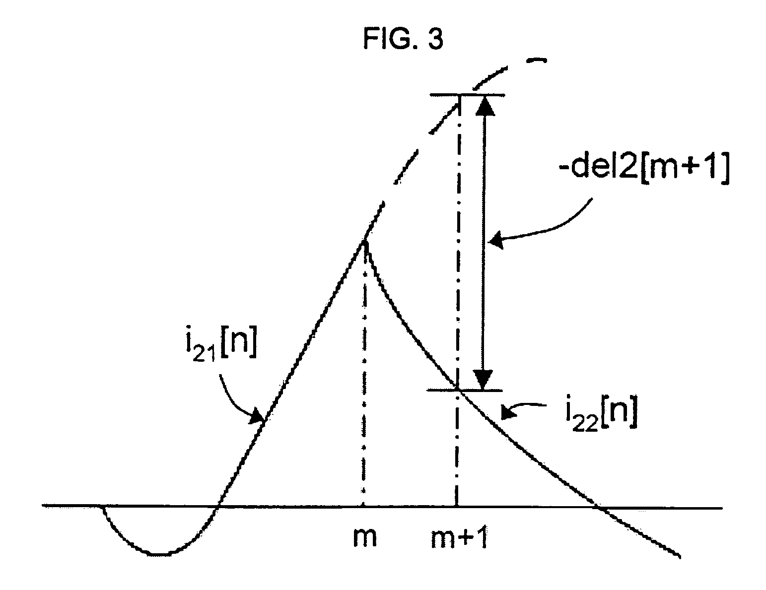
[0029]FIG. 3 exemplarily shows the transition of secondary currents i2[n] (solid line) actually measured in the vicinity of the saturation starting point of a current transformer. The current transformer is saturated at the time n=m. Currents are measured after saturation. In this case, secondary currents measured before saturation are represented by i21[n] and secondary currents measured after saturation are represented by i22[n]. Since secondary currents i1[n] consistent with a current transformation ratio are actually measured secondary currents, that is, i2[n] measured before saturation, the actually measured secondary currents substantially consist with the i22[n] in the drawing, which reflect the secondary currents i1[n] consistent with the current transformation ratio. After saturation, a secondary currents i1[n] consistent with a current transformati...


PUM


Abstract

A method for preventing the unwanted maloperation of a protective relay system that is caused by the imprecise detection of an actual secondary current value resulting from a measured secondary current being distorted comprises the steps of calculating difference values for sampled secondary currents; comparing absolute values of the difference values with a predetermined critical value, and determining a saturation starting moment of a current transformer when one of the absolute values exceeds the predetermined critical value; obtaining a magnetizing current at the saturation starting moment using the difference values if the saturation starting moment is determined, and obtaining a magnetic flux value in a steel core of the current transformer from a magnetization curve using the magnetizing current; calculating a magnetic flux value at a time after the saturation starting moment using a secondary current value measured at that time and the magnetic flux value obtained at the saturation starting moment so as to obtain a secondary current value consistent with a current transformation ratio at that time; obtaining a magnetizing current at that time from the magnetization curve using the magnetic flux value calculated at that time; and obtaining the secondary current value consistent with the current transformation ratio by adding the obtained magnetizing current and the measured secondary current value.

Description

TECHNICAL FIELD[0001]The present invention relates generally to a method of compensating the secondary currents of current transformers in a protective relay system for protecting a power system, and, more particularly, to a method of compensating the secondary currents of current transformers, which can make it possible to obtain precise secondary current values consistent with a current transformation ratio even during the saturation of a current transformer so as to prevent the unwanted maloperation of a protective relay system that is caused by the imprecise detection of an actual secondary current value resulting from a measured secondary current being distorted because a current transformer is saturated by a fault current.BACKGROUND ART[0002]A current transformer is an apparatus for measuring a current flowing through a power system and inputting the measured current to a protective relay system. As shown in FIG. 1, the current transformer comprises a core 34 for concentrating...

Claims


Application Information

Patent Timeline
Patent Type & Authority Patents(United States)
IPC IPC(8): G06F17/13H02H1/00H02H1/04
CPCH02H1/046H02H1/0092
Inventor KANG, YONG-CHEOLKANG, SANG-HEELIM, YI-JAE
Owner HANKOOK IED
Why Eureka
Try Eureka