Replica bias regulator with sense-switched load regulation control

a load regulation and bias regulator technology, applied in the field of replica bias regulators, can solve problems such as large load regulation, unstable loop, and change in voltag

Active Publication Date: 2006-09-12
MONTEREY RES LLC
View PDF8 Cites 39 Cited by
  • Summary
  • Abstract
  • Description
  • Claims
  • Application Information

AI Technical Summary

Benefits of technology

[0013]According to another broad aspect of another embodiment of the present invention, disclosed herein is a method of performing load regulation in a circuit. In one example, the method includes sensing a level of an output load current; and in response to the sensing operation, altering a feedback resistance in the replica bias circuit.
[0014]In one example, the altering operation may include bypassing a portion of the feedback resistance if the output load current is low, including a portion of the feedback resistance if the output load current is high.
[0015]According to another broad aspect of another embodiment of the present invention, disclosed herein is a circuit for performing load regulation of an output, comprising means for sensing a level of an output load current; and means for altering a feedback resistance in a replica bias circuit responsive to the sensing means. In one example, the means for altering may include means for bypassing a portion of the feedback resistance if the output load current is low, or may include means for including a portion of the feedback resistance if the output load current is high. The means for bypassing may include a comparator coupled with a switch.

Problems solved by technology

If the output node was in the loop, the loop could become unstable due to widely varying and unpredictable currents drawn by the load.
As recognized by the present inventor, the problem with this architecture is the large load regulation that results from the change in voltage at this node due to a change in current.
With large ranges of output currents, this architecture may not meet the output voltage requirements for all desired operating conditions.
However, when doing this, a new problem is created.
This range of problems effects applications where large ranges of current are required such as those with standby modes and active modes.

Method used


Image

  • Replica bias regulator with sense-switched load regulation control
  • Replica bias regulator with sense-switched load regulation control
  • Replica bias regulator with sense-switched load regulation control

Examples


Embodiment Construction

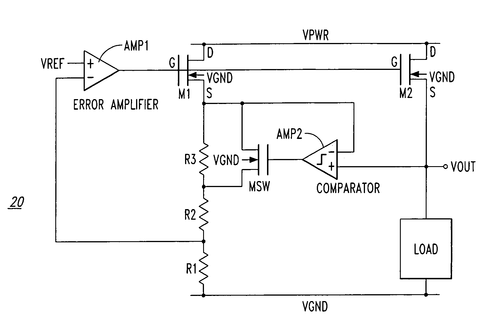
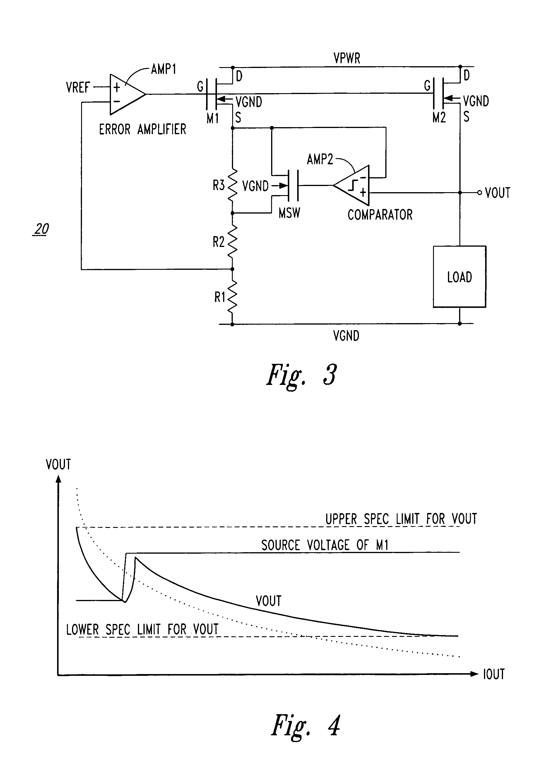
[0021]An example of an improved replica bias regulator 20 is shown in FIG. 3 in accordance with one embodiment of the present invention. This improved replica bias regulator includes circuitry to increase the range of load current the regulator can handle while staying within output voltage specification requirements. Various embodiments of the present invention will now be described.

[0022]In the example of FIG. 3, N-channel transistors M1 and M2 each have their drains coupled with a supply Vpwr and the gates of both transistors M1 and M2 are coupled with the output of amplifier AMP1 (i.e., an error amplifier). Amplifier AMP1 receives at its input a reference voltage, as well as a signal derived from the series combination of resistors R2, R1 which are coupled between the source of transistor M1 and ground. The source of transistor M2 is coupled with the load, and the source of transistor M2 provides the output voltage shown as Vout.

[0023]Further, resistor R3 is coupled between the ...


PUM


Abstract

A regulator circuit including output loading sense circuitry where the output loading sense circuitry comprises, in one example, a resistor in the feedback leg of the replica bias regulator, a switch in the feedback leg of the replica bias regulator for bypassing the resistor, and a comparator used to sense the output loading and selectively drive the switch.

Description

CROSS REFERENCE TO RELATED APPLICATION[0001]This application claims priority under 35 U.S.C. 119(e) to U.S. Provisional Patent Application No. 60 / 527,150 entitled “Replica Bias Regulator with Sense-Switched Load Regulation Control” filed Dec. 5, 2003, the disclosure of which is hereby incorporated by reference in its entirety.FIELD OF THE INVENTION[0002]The present invention relates generally to electronic circuits and in particular to circuits for replica bias regulation.BACKGROUND OF THE INVENTION[0003]A replica bias regulator is a regulator that isolates the output of the regulator from the feedback loop of the regulator. This is done to ensure stability of the feedback loop of the overall regulator. If the output node was in the loop, the loop could become unstable due to widely varying and unpredictable currents drawn by the load. The output voltage is then designed to be a replica (copy) of the voltage formed in the feedback loop that does not have varying current.[0004]A conv...

Claims


Application Information

Patent Timeline
Patent Type & Authority Patents(United States)
IPC IPC(8): G05F3/16
CPCG05F3/262G05F1/575
Inventor JACKSON, SCOTT A.
Owner MONTEREY RES LLC
Why Eureka
Try Eureka