Axle assembly with bearing adjustment mechanism

a technology of bearing adjustment mechanism and axle assembly, which is applied in the direction of bearing unit rigid support, gearing details, gearing, etc., can solve the problems of difficult deflecting clip step, time-consuming and complicated assembly process,

Active Publication Date: 2006-09-19
AMERICAN AXLE & MFG
View PDF21 Cites 63 Cited by
  • Summary
  • Abstract
  • Description
  • Claims
  • Application Information

AI Technical Summary

Benefits of technology

[0006]The present invention provides an axle assembly for a motor vehicle including an axle housing, a differential assembly supported in the axle housing with a differential bearing, a bearing insert and a lock ring. The bearing insert is coupled to the axle housing. An adjuster sleeve is rotatably coupled to the bearing insert in a pre-installed position. The adjuster sleeve is adapted to engage the differential bearing and impart a preload force thereon. The lock ring is press-fit between the bearing insert and the adjuster sleeve in an installed position. The lock ring precludes relative movement between the bearing insert and the adjuster sleeve thereby maintaining a desired preload on the differential bearing.

Problems solved by technology

While the aforementioned arrangement has been useful in retaining the differential bearings at the desired location, the assembly process is complicated and time consuming due to the alignment of the clip relative to adjacent castle extensions.
Furthermore, the step of deflecting the clip can be difficult and may require an installer to back-off or further tighten the adjuster sleeve to align respective castles on the adjuster sleeve for receipt of the clip.

Method used


Image

  • Axle assembly with bearing adjustment mechanism
  • Axle assembly with bearing adjustment mechanism
  • Axle assembly with bearing adjustment mechanism

Examples


Embodiment Construction

[0019]The following description of the preferred embodiment(s) is merely exemplary in nature and is in no way intended to limit the invention, its application, or uses.

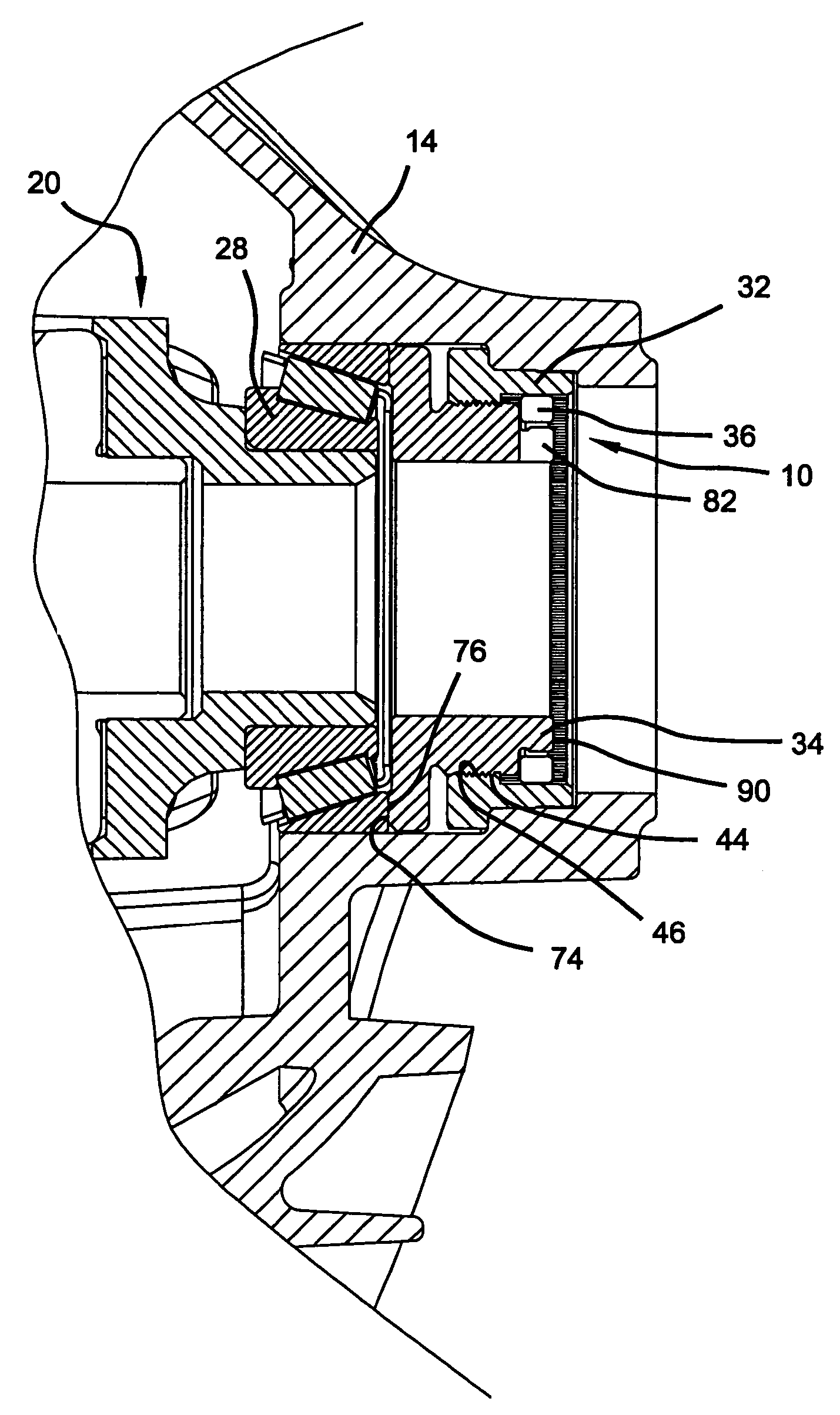
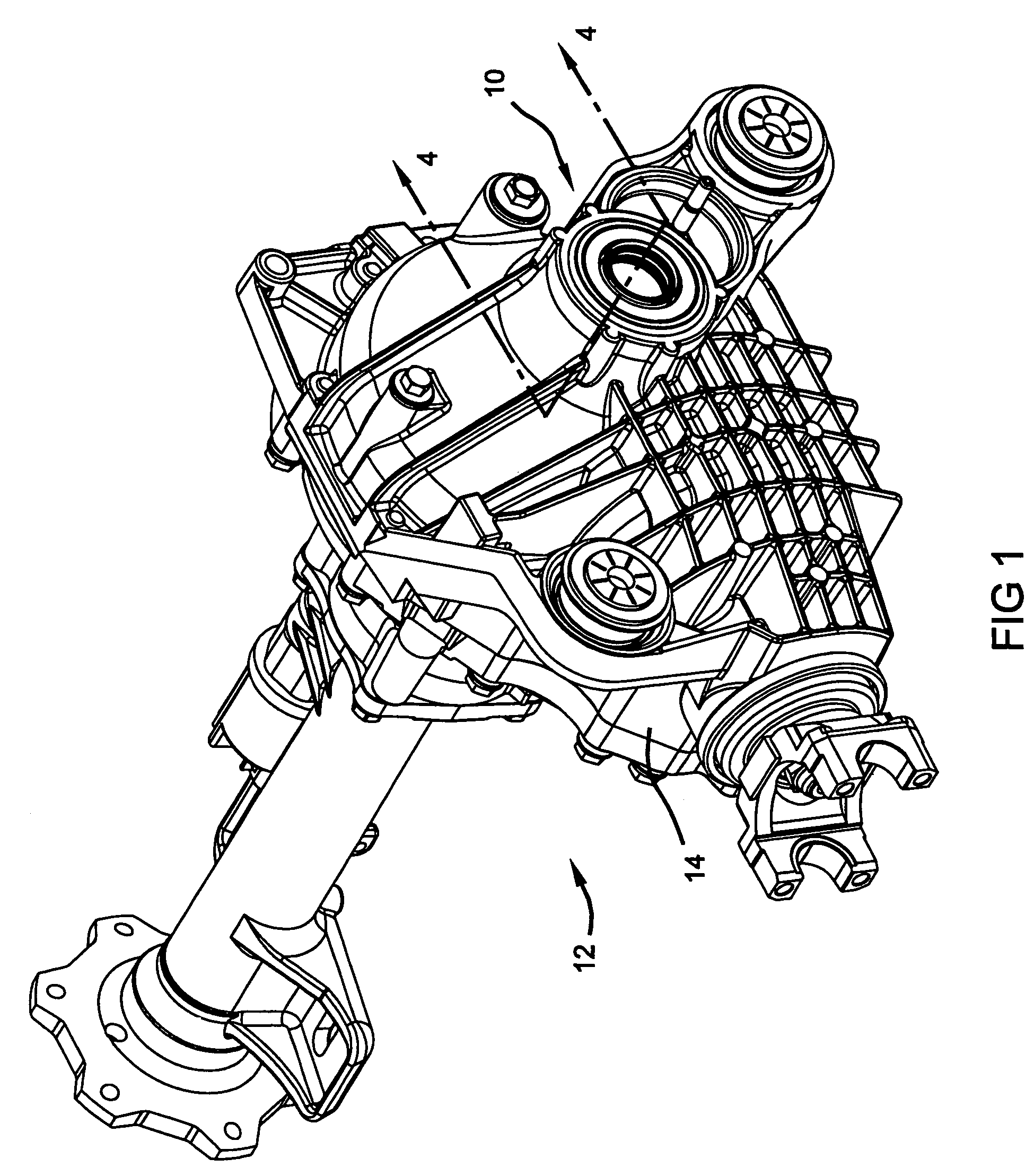
[0020]With initial reference to FIGS. 1 and 2, a differential bearing adjuster lock assembly constructed in accordance with the teachings of an embodiment of the present invention is generally identified at reference numeral 10. The adjuster lock assembly 10 is shown operatively associated with an exemplary drive axle assembly 12.

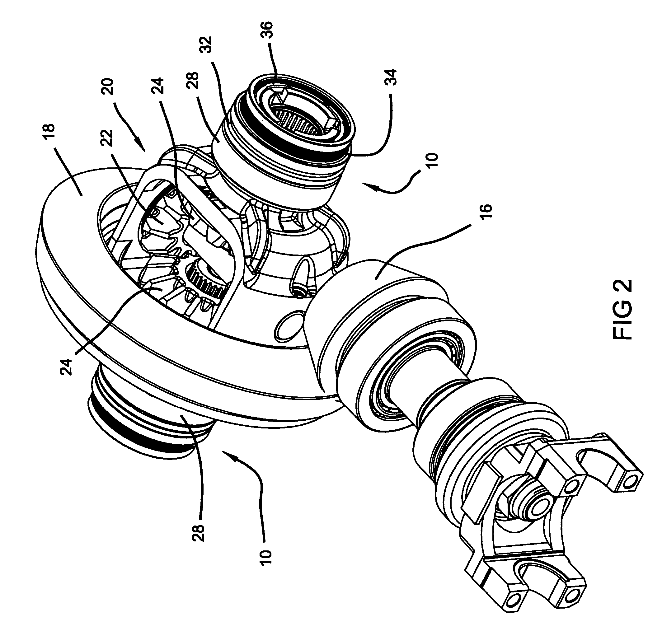
[0021]As particularly shown in FIGS. 1 and 2, the drive axle assembly 12 is illustrated to generally include an axle housing 14 for rotatably mounting a hypoid gear set including a pinion gear 16 and a ring gear 18 drivingly interconnected to a differential assembly 20. The differential assembly 20 functions to transfer power to a pair of axle shafts (not shown) while compensating for any difference in axle shaft speed rotation as may occur during a turn or other steering maneuver. In order t...


PUM

PropertyMeasurementUnit
inner diameteraaaaaaaaaa
outer diameteraaaaaaaaaa
retention forceaaaaaaaaaa

Abstract

The present invention provides an axle assembly for a motor vehicle including an axle housing, a differential assembly supported in the axle housing with a differential bearing, a bearing insert, an adjuster sleeve and a lock ring. The bearing insert is coupled to the axle housing. The adjuster sleeve is rotatably coupled to the bearing insert in a pre-installed position. The adjuster sleeve is adapted to engage the differential bearing and impart a preload force thereon. The lock ring is disposed between the bearing insert and the adjuster sleeve in an installed position. The lock ring precludes relative movement between the bearing insert and the adjuster sleeve thereby maintaining a desired preload on the differential bearing.

Description

FIELD OF THE INVENTION[0001]The present invention relates generally to differentials for use in automotive drivelines and, more particularly, to an arrangement and method for setting a differential bearing preload.BACKGROUND OF THE INVENTION[0002]Some automotive drive axles include a differential assembly including a gear set which is supported within a differential housing to facilitate relative rotation between a pair of output shafts. The gear set typically includes a pair of helical side gears that are splined to the ends of axle shafts. The helical side gears are meshed with paired sets of helical pinions generally supported on a cross pin coupled to the differential housing. In response to speed differentiation between the output shafts, torque transmitted through meshed engagement of the side gears and pinions generates thrust forces that are exerted by the gear components against the wall surface of the differential housing to frictionally limit the speed differentiation and...

Claims


Application Information

Patent Timeline
Patent Type & Authority Patents(United States)
IPC IPC(8): F16C35/06F16H48/06
CPCF16C25/06F16H57/021F16H57/037Y10T29/497F16H2057/0221F16H2048/405F16H2057/02043F16C2229/00F16C2361/61B60K17/16
Inventor ASON, RICHARD A.JACKSON, JEFFREY S.
Owner AMERICAN AXLE & MFG
Why Eureka
Try Eureka