Mailpiece perforating/cutting system

a perforating/cutting system and mailpiece technology, applied in the direction of envelope openers, manufacturing tools, instruments, etc., can solve the problems of time-consuming process, unscrupulous individuals may attempt to use the postal delivery system as a vehicle, and clear potential for significant health risks

Inactive Publication Date: 2006-09-26
PITNEY BOWES INC
View PDF23 Cites 3 Cited by
  • Summary
  • Abstract
  • Description
  • Claims
  • Application Information

AI Technical Summary

Problems solved by technology

Recent events have led to the realization that unscrupulous individuals may attempt to use the postal delivery system as a vehicle for spreading terrorism.
While the extent of damage that may occur by using mailpieces as a carrier of biological agents has yet to be determined, the

Method used


Image

  • Mailpiece perforating/cutting system
  • Mailpiece perforating/cutting system
  • Mailpiece perforating/cutting system

Examples


first embodiment

[0041]Referring specifically to FIGS. 9–11, the cutter wheels 803, 805 shall be discussed. Belt 821 is driven by a motor 843 via a pulley and belt system 844 and a shaft 845 in order to drive individual mailpieces 87 into a nip 846 defined between the cutting edges 847 and 849 of respective cutter wheels 803, 805. As belt 821 is driven, so is the cutting wheel 805 which is also mounted on shaft 845. The overlap of the cutting edges 847 and 849 also causes a rotation of cutter wheel 803 about a shaft 848. Accordingly, as the mailpieces 87 are fed along the arrow “A” into nip 846, the bottom of the mailpieces 87 is cut by the interaction of edges 847, 849 to produce the slots 851 shown in FIG. 11. The ability to produce the slots 851 is made by providing the cutter wheel 803 with notches 855 that are located around the perimeter of the cutter wheel 803. The notches 855 provide areas 857 of discontinuity in the cutting edge 847. It is the discontinuities 857 that produce corresponding ...

second embodiment

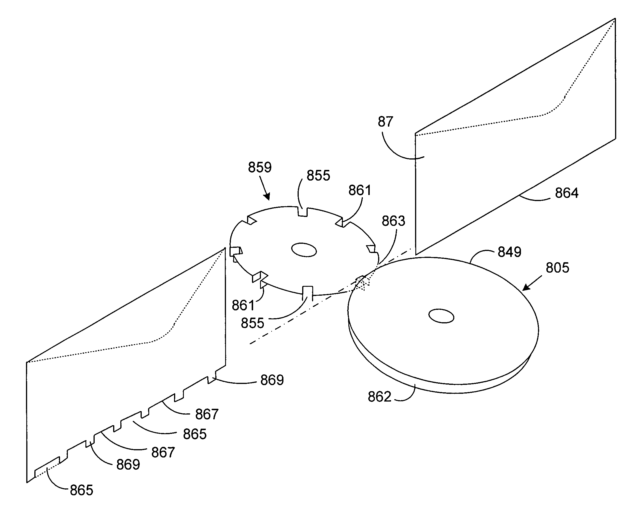
[0043]FIG. 12 shows a second embodiment where the cutter wheel 803 has been replaced by the cutter wheel 859. The cutter wheel 859 is similar to the cutter wheel 803 but further includes vertically extending cutting edges 861 at each side of the notches 855. Further, a circular urethane wheel 862 (backing member) has been mounted on shaft 845 directly below cutter wheel 805 to rotate therewith. Accordingly, as the mailpieces 87 pass between a nip 863 the bottom of the mailpiece 87 is cut in a castellated appearance whereby a plurality of segments 865 of the lower edge 864 have been removed to produce a plurality of edge openings 867. The openings 867 allow any powder material to pass therethrough during the jogging and compression / decompression cycles while the uncut edge segments 869 retain the contents within the mailpiece 87. Once again, the opened area of the mailpieces 87 are significantly increased over a cut corner opening to allow more opportunity for powder material to esca...


PUM


Abstract

A method for expelling air out of mailpieces includes the steps of creating a stack of the mailpieces; cutting an opening in at least some of the mailpieces; jogging the stack of mailpieces; and subjecting the stack of mailpieces to at least one compression/decompression cycle during the jogging step thereby expelling air out of the at least some of the mailpieces through their corresponding openings.

Description

BACKGROUND OF THE INVENTION[0001]The instant invention relates to systems for expelling powder materials from mailpieces. More particularly, the instant invention pertains to a cutting system that cuts openings in mailpieces to permit the expulsion of air and powder from the mailpieces while maintaining the privacy of the contents of the mailpieces.[0002]Recent events have led to the realization that unscrupulous individuals may attempt to use the postal delivery system as a vehicle for spreading terrorism. These individuals have, for example, contaminated mailpieces with biological agents (such as anthrax) and distributed such mailpieces to targeted locations via the postal service. While the extent of damage that may occur by using mailpieces as a carrier of biological agents has yet to be determined, the potential for significant health risks is clear. Accordingly, increased efforts have been set forth toward the development of systems and processes that may be effective in detec...

Claims


Application Information

Patent Timeline
IPC IPC(8): B23D5/00B65G1/00A61L2/08B43M7/00G01N1/02
CPCA61L2/087B43M7/008G01N2001/025A61L2202/14Y10T83/4838Y10T83/483Y10T83/4798Y10T83/647Y10T83/9408
Inventor BELEC, ERIC A.FARRELL, MICHAEL M.GATEMAN, JEFFREY A.MILLER, EDWARD C.STEMMLE, DENIS J.
Owner PITNEY BOWES INC
Why Eureka
Try Eureka