
Thread former or tap

a technology of thread formers and taps, applied in the field of thread formers or taps, can solve the problems of no material removal, relatively high manufacturing cost of thread forming taps and screw taps, and no tool is more useful

Inactive Publication Date: 2006-09-26
FETTE
View PDF22 Cites 31 Cited by
  • Summary
  • Abstract
  • Description
  • Claims
  • Application Information

AI Technical Summary

Benefits of technology

[0016]In the invention, it was found that with modern machine tools, more or less long guiding portions on cold thread forming taps or screw taps are no more necessary in order to turn out the tool without damaging the thread, when screwing it out of the produced thread bore.

Problems solved by technology

However, they do not remove any material, but only displace it.
Thread forming taps and screw taps are relatively expensive to manufacture and consist of a high-quality material, as the case may be.
After wear or damage, the tool is no more useful.

Method used


Image

  • Thread former or tap
  • Thread former or tap
  • Thread former or tap

Examples


Embodiment Construction

[0033]While this invention may be embodied in many different forms, there are described in detail herein a specific preferred embodiment of the invention. This description is an exemplification of the principles of the invention and is not intended to limit the invention to the particular embodiment illustrated.

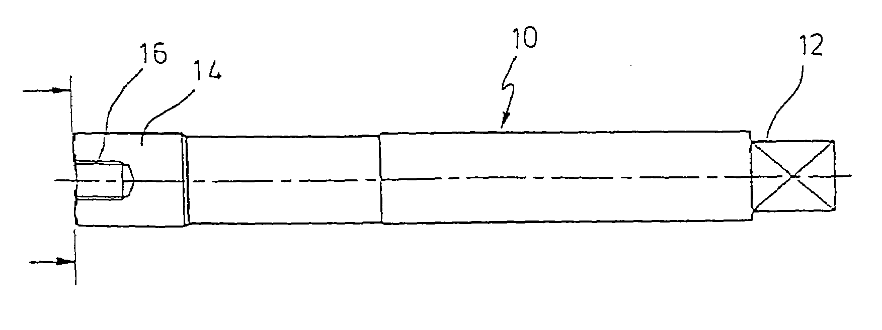
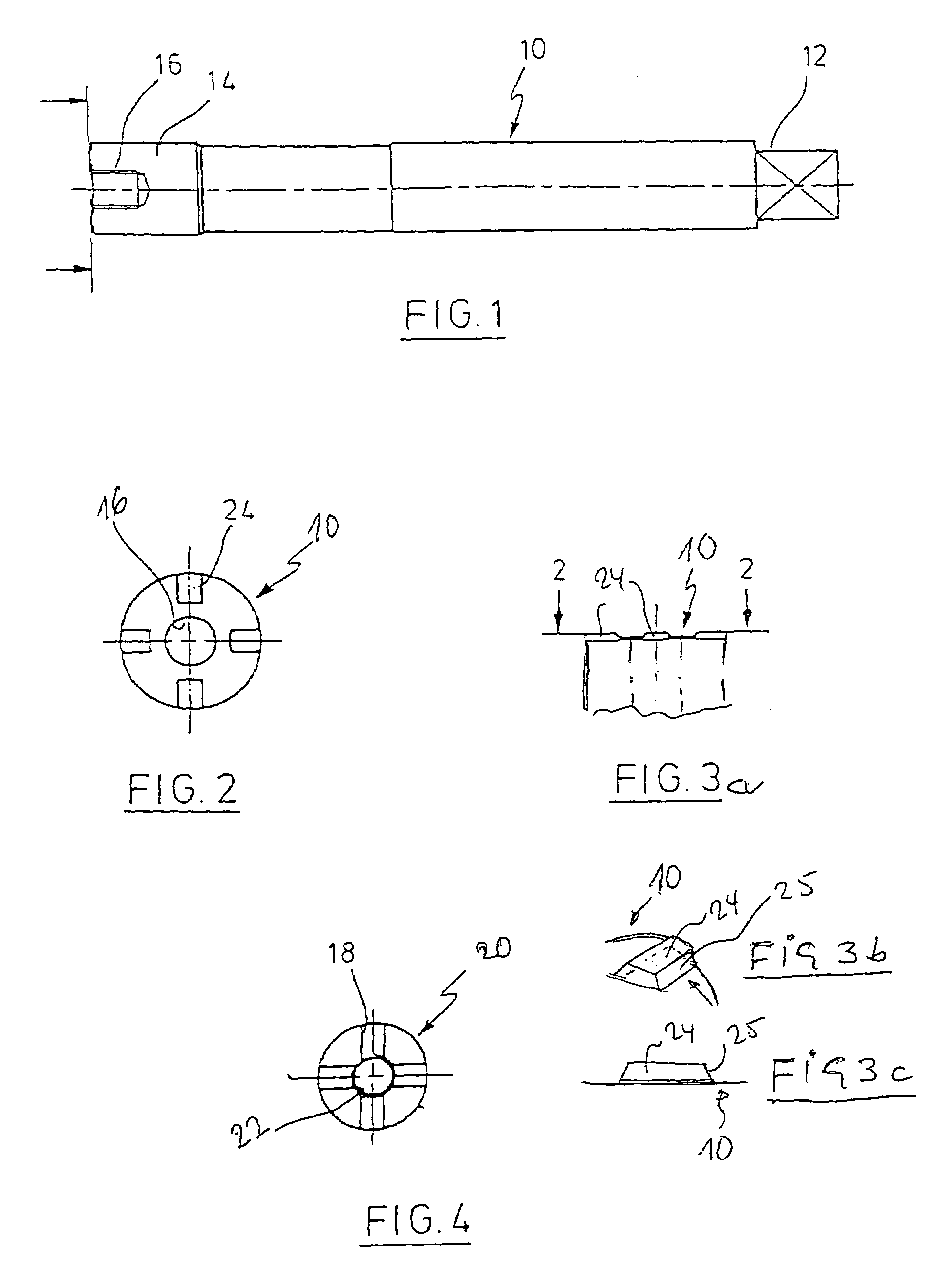
[0034]In FIG. 1, a tool shaft 10 is represented which has a chuck portion 12 on the one end and on the other end a portion 14 for connection with a profile element after FIG. 4. From the end view of shaft 10 after FIG. 2 one can recognise that it has a centric thread bore 16 and crosswise arranged ribs 24, the cross of the ribs 24 coinciding in its centre point with the axis of the shaft 10 or the bore 16, respectively.

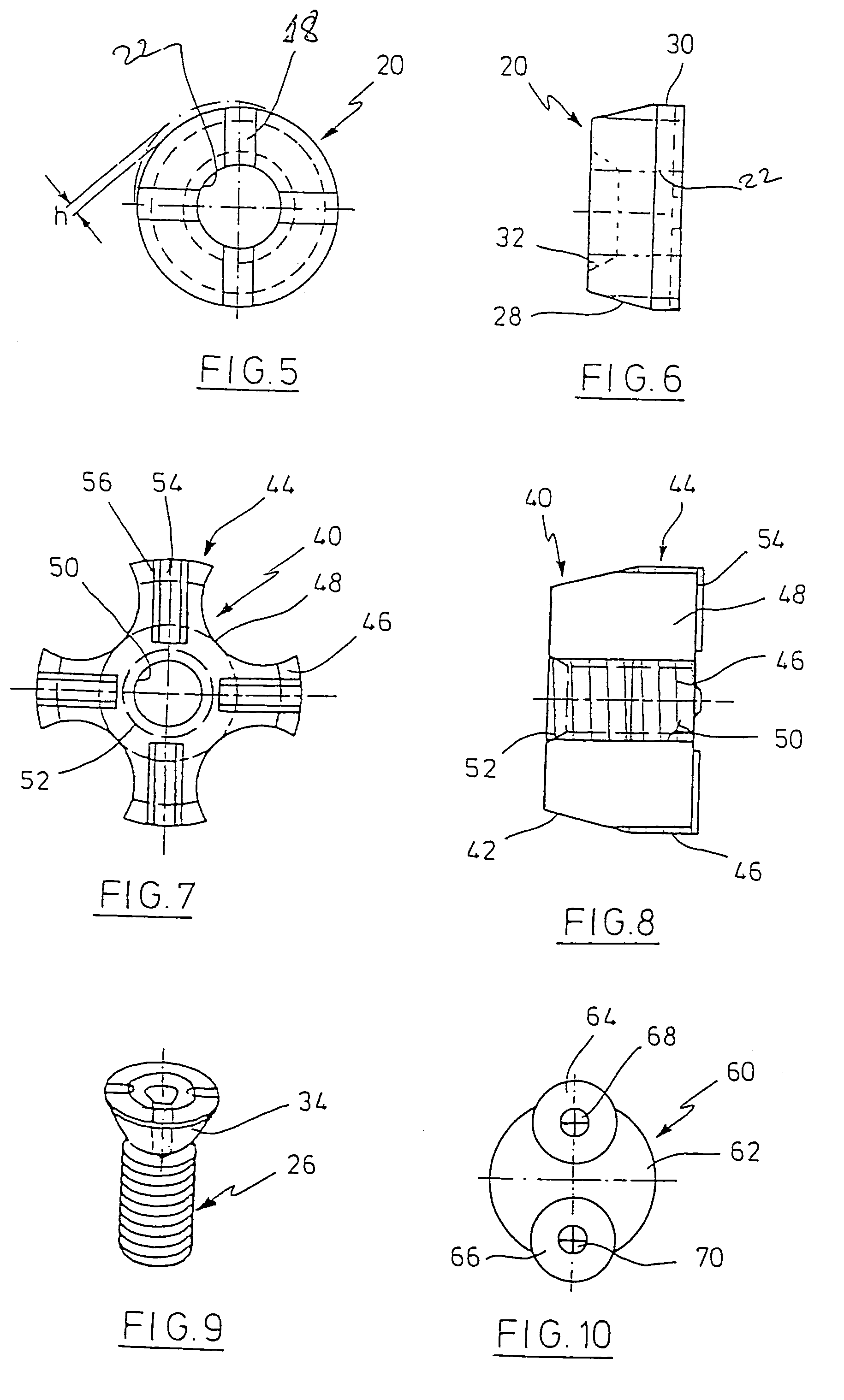
[0035]In FIG. 4, a plate-shaped forming profile element 20 is represented, which has a forming initiation cone as well as a thread profile (not shown) for the making of an interior thread according to the cold form grooving or thread forming method. The perimet...


PUM

PropertyMeasurementUnit
axial lengthaaaaaaaaaa
areasaaaaaaaaaa
diameteraaaaaaaaaa

Abstract

Cold thread forming tap or screw tap with a shaft, said shaft having a chuck portion at the one end and a forming or cutting profile portion on the other end, the forming or cutting profile portion being realised as a separate profile element and being fixable centrically and secured against rotation on the shaft by means of a fixing device, characterised in that the profile element has a small axial length and on the outside a lead-in or starting tap cone, respectively, that juts and / or indentations are formed at the end of the shaft and on that side of the profile element facing the shaft, which interlock in a positively fitting manner, that an automatic centring of the profile element takes place on the shaft when the profile element is put onto the shaft.

Description

CROSS-REFERENCE TO RELATED APPLICATIONS[0001]This application is the National Stage filing under 35 U.S.C. 371 from PCT / EP02 / 01913 now PCT Publication No. WO03 / 011508 having an international filing date of Jul. 17, 2002, claiming priority from German Application No. DE2001010136293.5 filed Jul. 25, 2001, now German Patent No. DE3934621 published on Sep. 4, 1997, on behalf of Fette GmbH, the entire contents of which are hereby incorporated herein in their entireties.STATEMENT REGARDING FEDERALLY SPONSORED RESEARCH[0002]Not ApplicableBACKGROUND OF THE INVENTION[0003]It is known to create interior (or female) threads with the aid of a screw tap or a thread forming tap. Screw taps evolve from screw bolts by generating cutting edges through the introduction of axis parallel or slant flutes. In the lead-in region, a so-called starting taper is provided, which is mostly realised in conical form. The hole in the workpiece is pilot-drilled with the core diameter.[0004]Thread forming taps are...

Claims


Application Information

Patent Timeline
Patent Type & Authority Patents(United States)
IPC IPC(8): B21J13/02B23G5/06B23G7/02
CPCB23G5/06B23G7/02B23G2200/02
Inventor MULLER, WOLFGANG
Owner FETTE
Learn More