System and method for selecting optimized beam configuration

Inactive Publication Date: 2006-10-03
F POSZAT HU
View PDF8 Cites 36 Cited by
  • Summary
  • Abstract
  • Description
  • Claims
  • Application Information

AI Technical Summary

Benefits of technology

[0018]Accordingly, a technical advantage of the present invention is that the use of optimized beams is provided such that the amount of interference energy radiated and/or accepted is controlled. Moreover, a technical advantage of the present invention is that system capacity increases may be accomplished while maintaining a desired signal quality.
[0019]A further technical advantage of the present invention is provided by the use of angle spread information in selecting optimized communication links to thereby provide a communication link adapted for use with a scattering zone experienced by a subscriber unit. Moreover, a technical advantage of the present invention is that communication links selected using such angle spread information

Problems solved by technology

For example, as communication capacity is increased, such as through more dense reuse of traffic channels, signal quality may be decreased, such as through each such traffic channel experiencing higher levels of interference energy.
Accordingly, wireless communication service providers must often balance providing desired levels of communication capacity with service quality issues.
However, despreading of the desired subscriber unit's signal results in the receiver not only receiving the energy of this desired signal, but also a portion of the energies of other subscriber units operating over the same frequency band.
However, the use of such directional antenna beams in the forward link often does not provide the desired containment of the radiated energy and/or does not provide a desired signal quality at a target remote subscriber unit.
This both results in a waste of the transmitted power as well as increased interference energy experienced at other ones of the subscriber units.
Increased interference energy experienced at the subscriber units results in decreased capacity, whether the decreased capacity is a result of fewer subscriber units being accommodated, the subscriber units being accommodated being provided decreased throughput, or a combination thereof.
This un

Method used


Image

  • System and method for selecting optimized beam configuration
  • System and method for selecting optimized beam configuration
  • System and method for selecting optimized beam configuration

Examples


Embodiment Construction

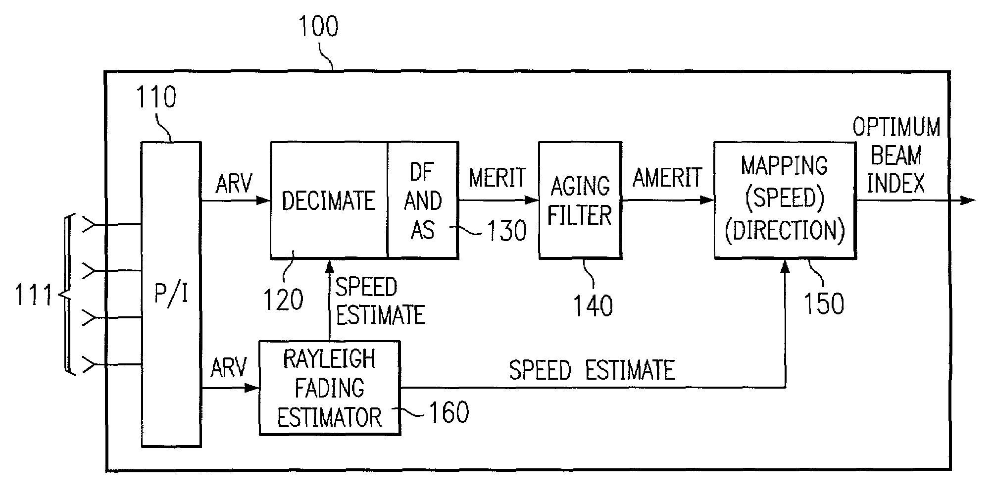
[0030]Directing attention to FIG. 1, a preferred embodiment beam correlator system of the present invention adapted to determine an optimal antenna beam configuration for use in a communication network, such as a cellular or Personal Communication Services (PCS) system, is shown generally as beam correlator 100. According to a preferred embodiment, an optimal antenna beam determined through use of beam correlator 100 is utilized in providing a forward link that results in a least transmit power required to maintain a desired signal quality, such as by maintaining a desired Frame Error Rate (FER). Of course, alternative embodiments of the invention may utilize beam correlator 100 differently, such as for determining reverse link beam configurations, and / or may utilized different metrics than those shown, such as maintaining a desired Bit Error Rate (BER), Receive Signal Strength Indicator (RSSI), Carrier to Interference (C / I) ratio, etcetera.

[0031]Preferred embodiment beam correlator...


PUM


Abstract

Disclosed are systems and methods which provide communication links optimized with respect to particular subscriber units. Preferred embodiments utilize multiple information components with respect to the arrival of signals associated with target subscriber units in providing optimized communication links. Most preferably, direction information and information with respect to the signal spread experienced in the communication channel is used. Moreover, preferred embodiments utilize subscriber unit speed information in providing optimized communication link determinations.

Description

CROSS-REFERENCE TO RELATED APPLICATIONS[0001]The present application is related to copending and commonly assigned U.S. patent application Ser. No. 09 / 229,482 entitled “Practical Space-Time Radio Method for CDMA Communication Capacity Enhancement” filed Jan. 13, 1999, which is a continuation-in-part of U.S. Pat. No. 6,108,565 entitled “Practical Space-Time Radio Method for CDMA Communication Capacity Enhancement,” application Ser. No. 09 / 803,718 entitled “Space-Time and Space-Frequency Hopping for Capacity Enhancement of Mobile Data Systems,” filed Mar. 9, 2001, and Ser. No. 09 / 803,356 entitled “System and Method for Providing Phase Matching with Optimized Beam Widths,” filed Mar. 9, 2001, the disclosures of all of which are hereby incorporated herein by reference.TECHNICAL FIELD[0002]The invention relates generally to wireless communications and, more particularly, to determining optimal beams to minimize transmit power while maintaining a desired signal quality.BACKGROUND OF THE I...

Claims


Application Information

Patent Timeline
IPC IPC(8): H04B1/38H04M1/00
CPCH04B7/0695H04B7/088H04W52/42
Inventor VAN RENSBURG, CORNELIUSWONG, PIU BILL
Owner F POSZAT HU
Why Eureka
Try Eureka