
Harvester reel tine repair

a technology of harvester reel and repair rod, which is applied in the field of harvester reel tine repair rod, can solve the problems of wasting both time and effort, affecting the efficient operation of harvester reel, and affecting the efficiency of harvester reel operation, so as to maximize the time, reduce the time and effort, and improve the effect of harvester reel efficiency

Inactive Publication Date: 2006-10-24
PLASTIC DESIGNS
View PDF18 Cites 19 Cited by
  • Summary
  • Abstract
  • Description
  • Claims
  • Application Information

AI Technical Summary

Benefits of technology

[0004]Once a sufficient number of tine fingers have been broken to impair the efficient operation of the harvester reel, it is necessary to stop the harvester and manually unscrew and remove the broken pickup tines from the support shaft and replace them with new tines. This obviously is wasteful of both time and effort, requires the use of a tool, and maximizes the time which the combine is out of service.
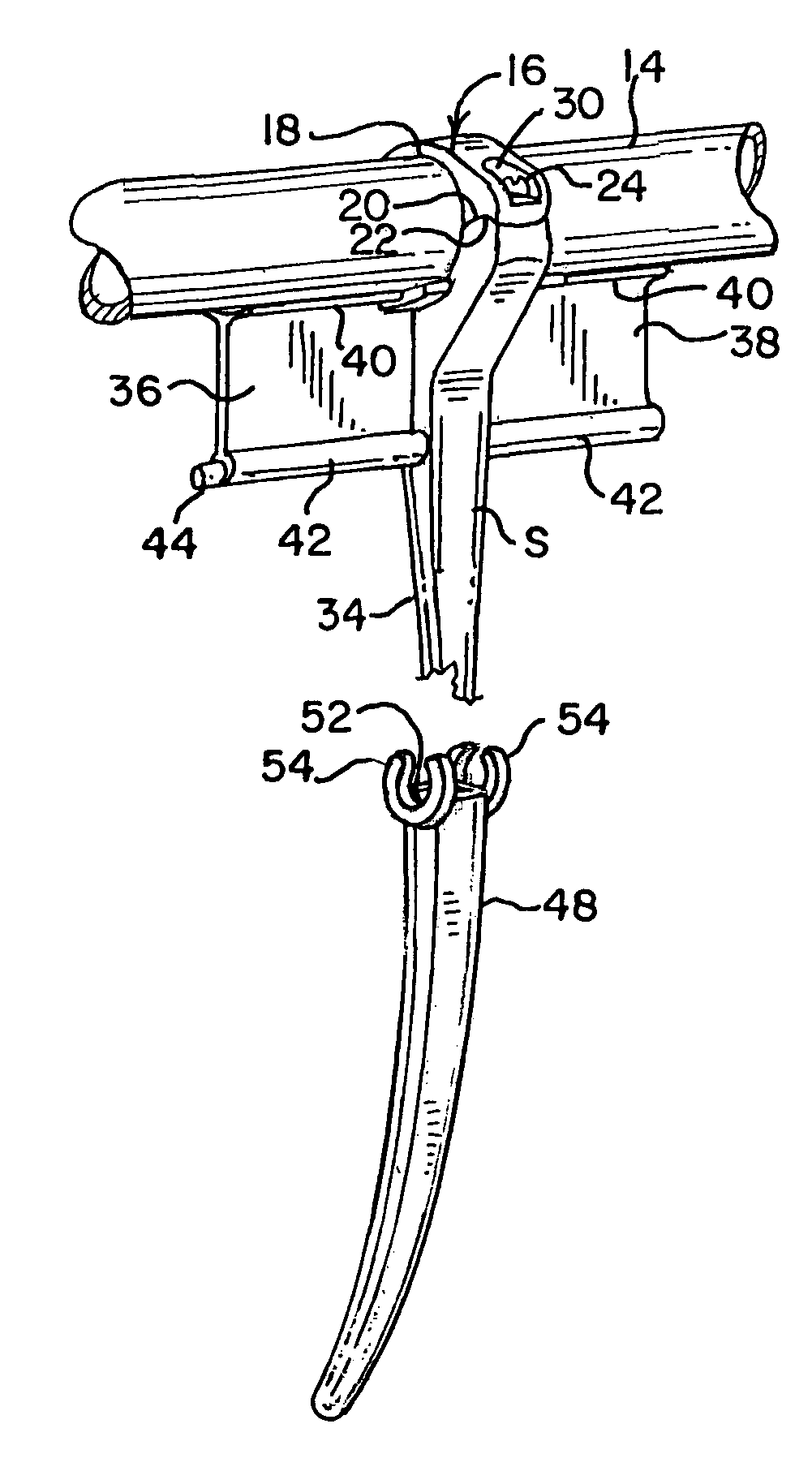
[0005]The present invention substantially reduces such waste of time, effort and downtime by permitting a broken tine finger to be easily and rapidly repaired without the need for tools or the need to remove the pickup tine from the support shaft and replace it with a new tine. In the present invention a new hollow finger is simply slipped over the remaining portion of the broken finger and is fastened in place to the existing tine without the need to remove the existing tine with its broken finger from the support shaft or the need for tools to do so. Moreover, if the hollow finger itself subsequently becomes broken, it may easily be replaced simply by removing it from the preexisting pickup tine and replacing the hollow finger with a new hollow finger.

Problems solved by technology

In view of the rather severe environment in which these pickup tines operate and their functional purpose, the fingers of the tines are subject to breakage due to contact with rocks and other objects as well as the crop which itself is being harvested all of which are encountered while the rotating harvester reel is moving over the field being harvested.
However, breakage of the fingers will inevitably occur.
This obviously is wasteful of both time and effort, requires the use of a tool, and maximizes the time which the combine is out of service.
Moreover, if the hollow finger itself subsequently becomes broken, it may easily be replaced simply by removing it from the preexisting pickup tine and replacing the hollow finger with a new hollow finger.

Method used


Image

  • Harvester reel tine repair
  • Harvester reel tine repair
  • Harvester reel tine repair

Examples


Embodiment Construction

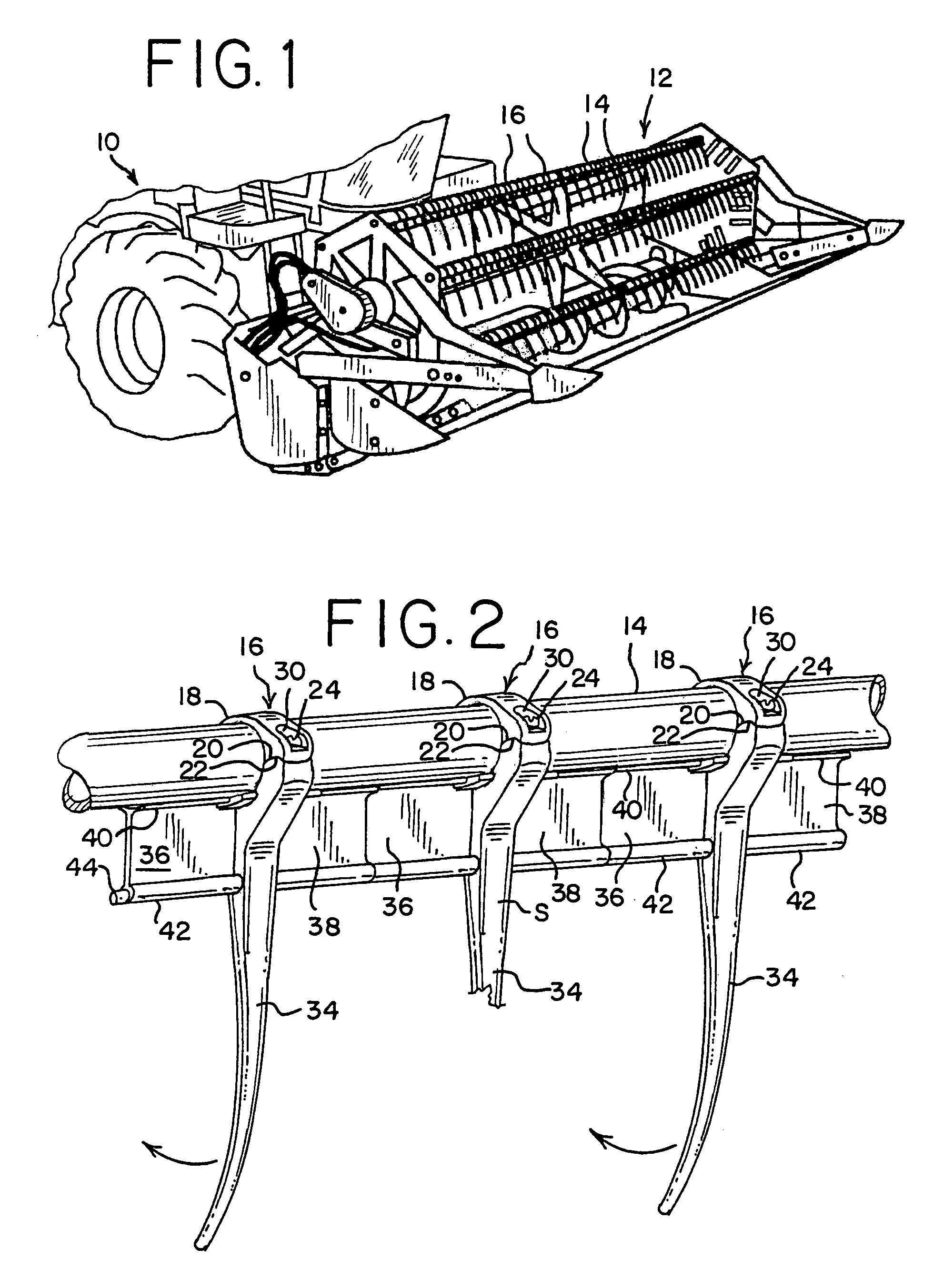
[0028]A combine 10 for harvesting a crop is partially shown in FIG. 1 having a harvester reel 12 at the forward end thereof for picking up the crop to be harvested for processing by the combine. Such crops typically include wheat, soybeans and other small grains. The harvester reel 12 is comprised of a plurality of horziontally extending spaced apart support shafts 14 which rotate as the reel 12 is rotated. Each of the support shafts 14 has a plurality of pickup tines 16 spaced at approximately equal distances from each other along the length of the support shaft 14 as best seen in FIGS. 1 and 2.

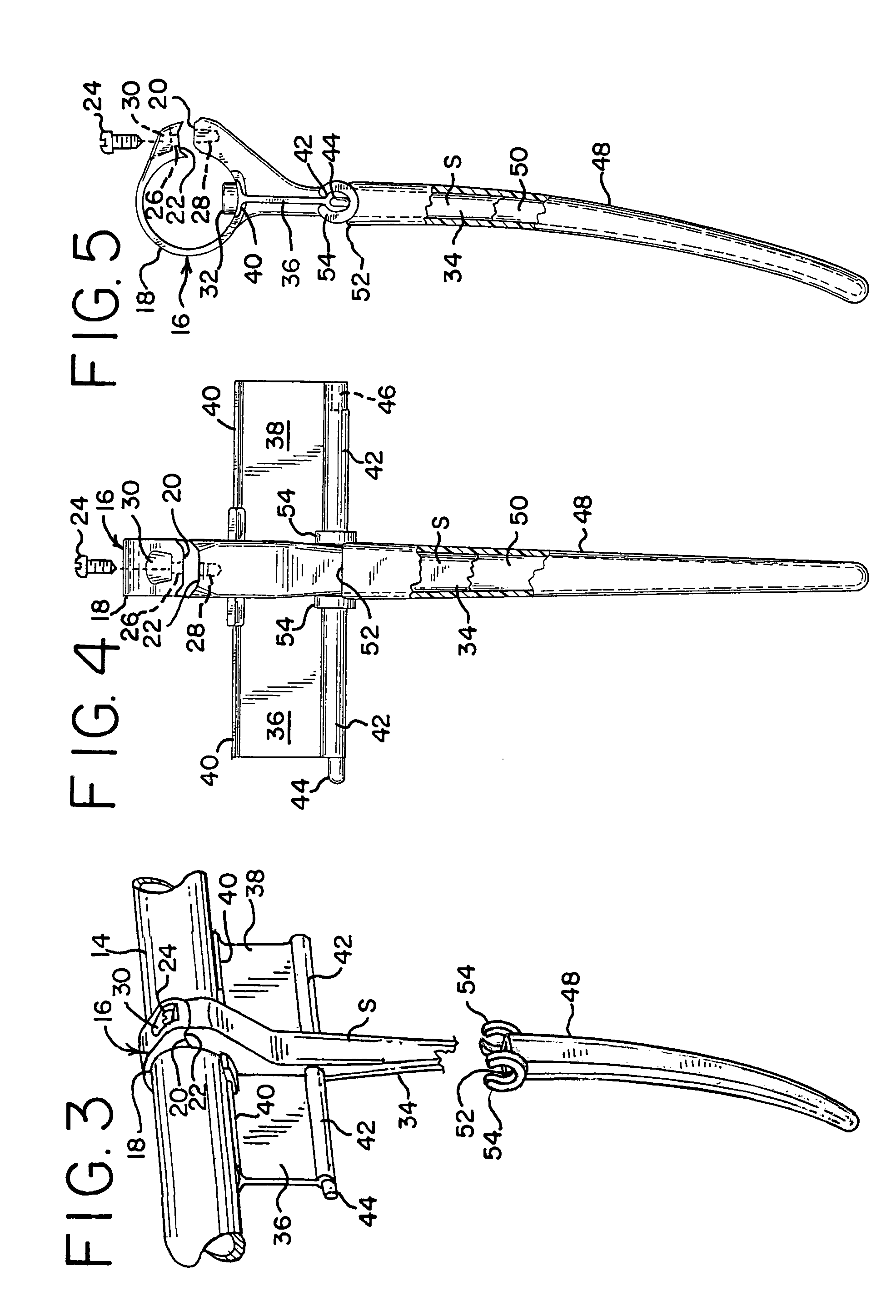
[0029]Each of the pickup tines 16 comprises a clamp 18 at one end which is preferably formed by a split ring which may be opened by flexing to present a pair of jaws 20 and 22 as seen in FIGS. 4 and 5 which may be further flexed to separate from each other to permit passage of the clamp 18 onto and around the support shaft 14. Once the clamp 18 has been positioned on the support shaft 14, th...


PUM


Abstract

Repair of a broken finger of a harvester reel pickup tine is accomplished by positioning a repair finger having a cavity over the broken finger stub so that the broken finger stub of the harvester reel pickup tine is received in the cavity of the repair finger, and the repair finger is then fastened adjacent one end to the pickup tine when the broken finger stub is in the cavity.

Description

BACKGROUND AND SUMMARY OF THE INVENTION[0001]The present invention is directed to the repair of broken harvester reel pickup tine fingers.[0002]Combines used in the harvesting for example of wheat, soy beans and small grains typically have a rotating cylindrical harvester reel at the forward leading end of the combine to sweep the crop which is to be harvested into the combine apparatus. These reels include a plurality of spaced horizontally extending support shafts which rotate with the reel and which have a plurality of pickup tines attached in side by side relationship to each other along the length of the support shafts. These pickup tines are typically molded in one piece integral construction of a durable plastic, such as for example, nylon, acetal or homopolypropylene, and include a clamp for clamping the pickup tine to the support shaft and an elongate curved finger of approximately 7½ inches long which extends from the clamp so as to sweep the crop to be harvested into the ...

Claims


Application Information

Patent Timeline
Patent Type & Authority Patents(United States)
IPC IPC(8): A01D57/02
CPCA01D57/02
Inventor GLAZIK, STEVEN G.GLAZIK, GARY B.
Owner PLASTIC DESIGNS
Learn More