Lighted headgear with motion activated switch

a technology of motion activated switch and headgear, which is applied in the direction of lighting device details, lighting support devices, lighting and heating apparatus, etc., can solve the problems of high ac voltage for operation, inconvenient use of incandescent bulbs, and relatively inefficient bulbs

Inactive Publication Date: 2006-10-31
SPORTSCRAFT
View PDF43 Cites 83 Cited by
  • Summary
  • Abstract
  • Description
  • Claims
  • Application Information

AI Technical Summary

Problems solved by technology

For example, incandescent bulbs are relatively inefficient and typically enclosed in glass which can be hazardous if broken.
Electroluminescent devices are viewable over wide angles and tend to be more efficient than incandescent bulbs but, unfortunately, require a relatively high AC voltage for operation which complicates their u

Method used


Image

  • Lighted headgear with motion activated switch
  • Lighted headgear with motion activated switch
  • Lighted headgear with motion activated switch

Examples


Embodiment Construction

[0023]Before explaining the present invention in detail, it is important to understand that the invention is not limited in its application to the details of the construction illustrated and the steps described herein. The invention is capable of other embodiments and of being practiced or carried out in a variety of ways. It is to be understood that the phraseology and terminology employed herein is for the purpose of description and not of limitation.

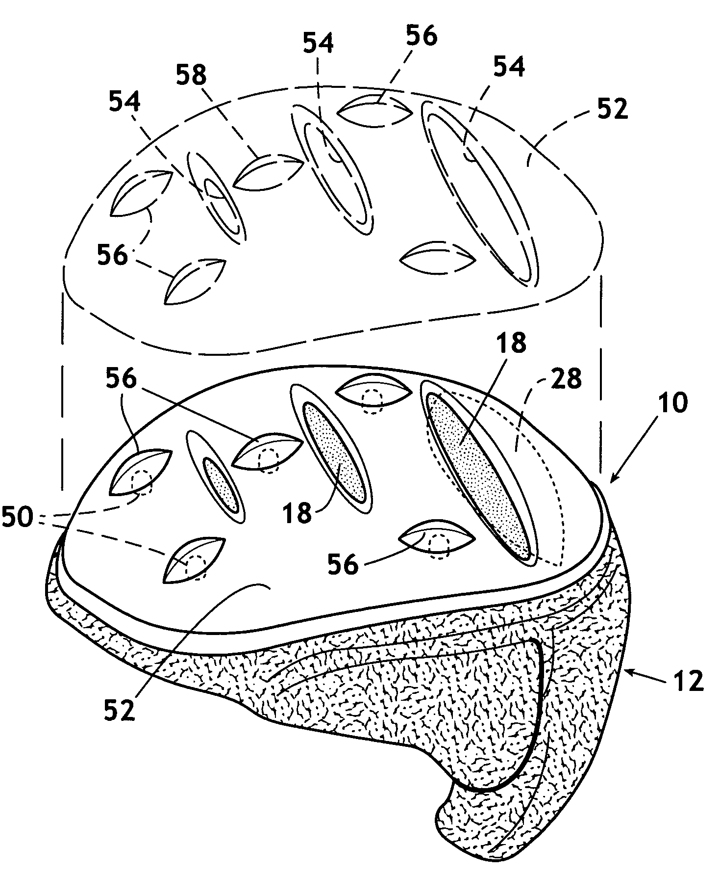
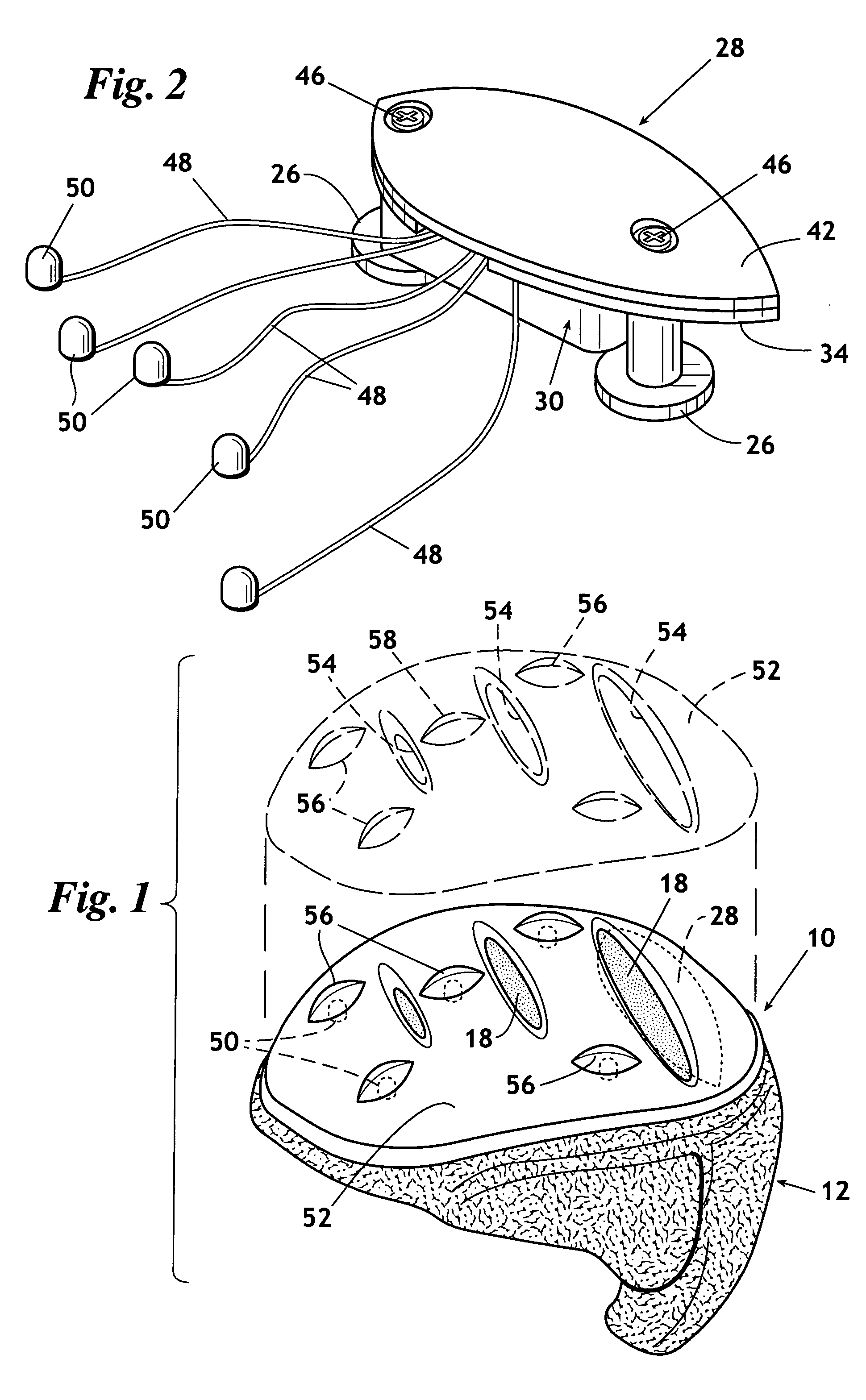
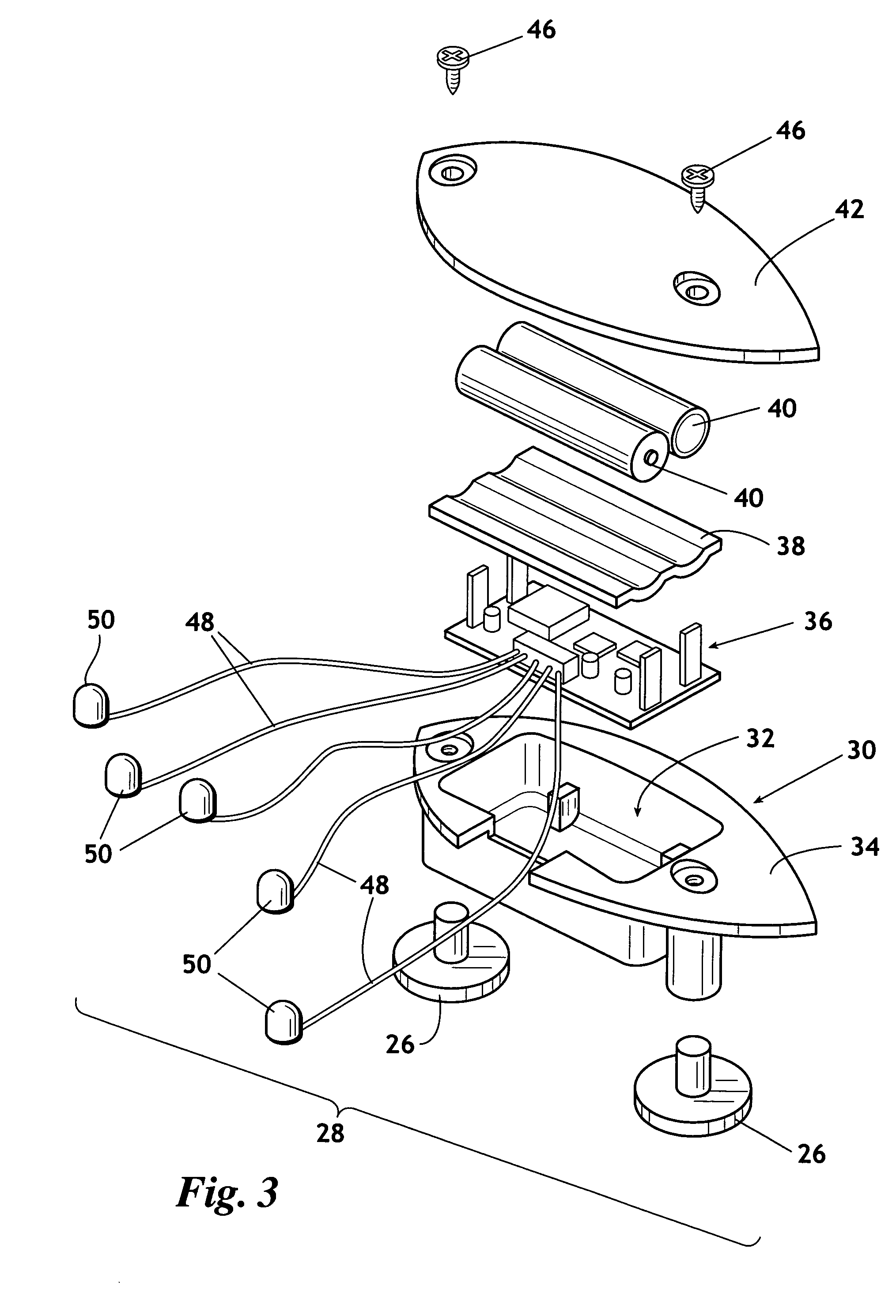
[0024]Referring to FIGS. 1–8, wherein like reference numerals indicate the same parts throughout the several views, a lighted helmet 10 is shown. Lighted helmet 10 includes a protective shell 12 (FIGS. 1, 7, and 8) that defines an inside surface 14 (FIG. 8), an outside surface 16 (FIGS. 7 and 8), and a plurality of vents 18. As best seen in FIG. 7, the outside surface 16 has a plurality of channels 20 formed therein. Channels 20 communicate with recessed areas 22. Outer surface 16 further defines a housing cavity 24.

[0025]Anchor membe...


PUM


Abstract

A lighted helmet having a protective shell having: an outside surface, a plurality of lamps which emit light from the outside surface; a power supply, typically a battery; and a motion detecting switch in communication with the power supply and the plurality of lamps. When the helmet is worn by a user, even small movements of the head produce forces, which in turn, trigger the motion detecting switch. Upon triggering of the motion detecting switch, the lamps are illuminated for a predetermined period of time. Upon expiration of the time period, subsequent motion will retrigger the switch, once again activating the lamps. The process continues until the helmet is placed in a stationary position, at which time the lamps are extinguished upon expiration of the then active time period.

Description

[0001]1. Field of the Invention[0002]This invention relates generally to illuminated safety helmets. More particularly, but not by way of limitation, the present invention relates to an illuminated bicycle helmet having a plurality of light emitting diodes activated via a motion detecting switch.[0003]2. Background[0004]Generally speaking, illuminated protective helmets, i.e. bicycle helmets and the like, are well known in the art. Properly crafted, such helmets may provide an added measure of safety through enticing the wearer to wear the helmet. Further, the helmets may be worn simply because such helmets can provide an expression of the individualism of the particular wearer. One often finds the illumination of such helmets integrated with the overall graphical presentation on the exterior of the helmet to complement the helmet's particular style.[0005]A number of lighting schemes have been used to illuminate helmets such as, for example, incandescent lights, electroluminescent l...

Claims


Application Information

Patent Timeline
IPC IPC(8): F21V21/084
CPCA42B3/044
Inventor NALLY, MICHAELLASATER, PENNY
Owner SPORTSCRAFT
Why Eureka
Try Eureka