Multi-purpose upright support stand with leg assemblies having hinge-fitting

a technology of hinge fitting and support stand, which is applied in the direction of stand/trestle, kitchen equipment, domestic applications, etc., can solve the problem of quite limited use of each of these stands

Inactive Publication Date: 2006-11-21
WILLEY KEVIN E
View PDF27 Cites 31 Cited by
  • Summary
  • Abstract
  • Description
  • Claims
  • Application Information

AI Technical Summary

Benefits of technology

[0011]As one will appreciate, certain of the several unique features, and further unique combinations of features, as supported and contemplated hereby may provide a variety of advantages including versatility of use / application, portability, and so on.
[0013](b) Compact, portable design is handy to set up, take down, move from place to place, as well as collapse for transport and / or storing; structure can be fabricated using lightweight plastics, metals / alloys, etc. (including the leg assemblies which can be built from tube stock of various cross-sectional shapes) that provide sufficient support in varying environments.

Problems solved by technology

While many of the current stand designs provide a certain basic amount of stability, each of these stands is quite limited in that each is designed to support the item for which it was specifically designed.
Furthermore, most all of these traditional stand designs cannot be set up on ground that is not planar and level; few of these conventional designs provide much, if any, support when a gust of wind or inclement weather hits (heavy wind, rain, etc.); and in most-every case, traditional stand designs are suitable for use to support a single article.

Method used


Image

  • Multi-purpose upright support stand with leg assemblies having hinge-fitting
  • Multi-purpose upright support stand with leg assemblies having hinge-fitting
  • Multi-purpose upright support stand with leg assemblies having hinge-fitting

Examples


Embodiment Construction

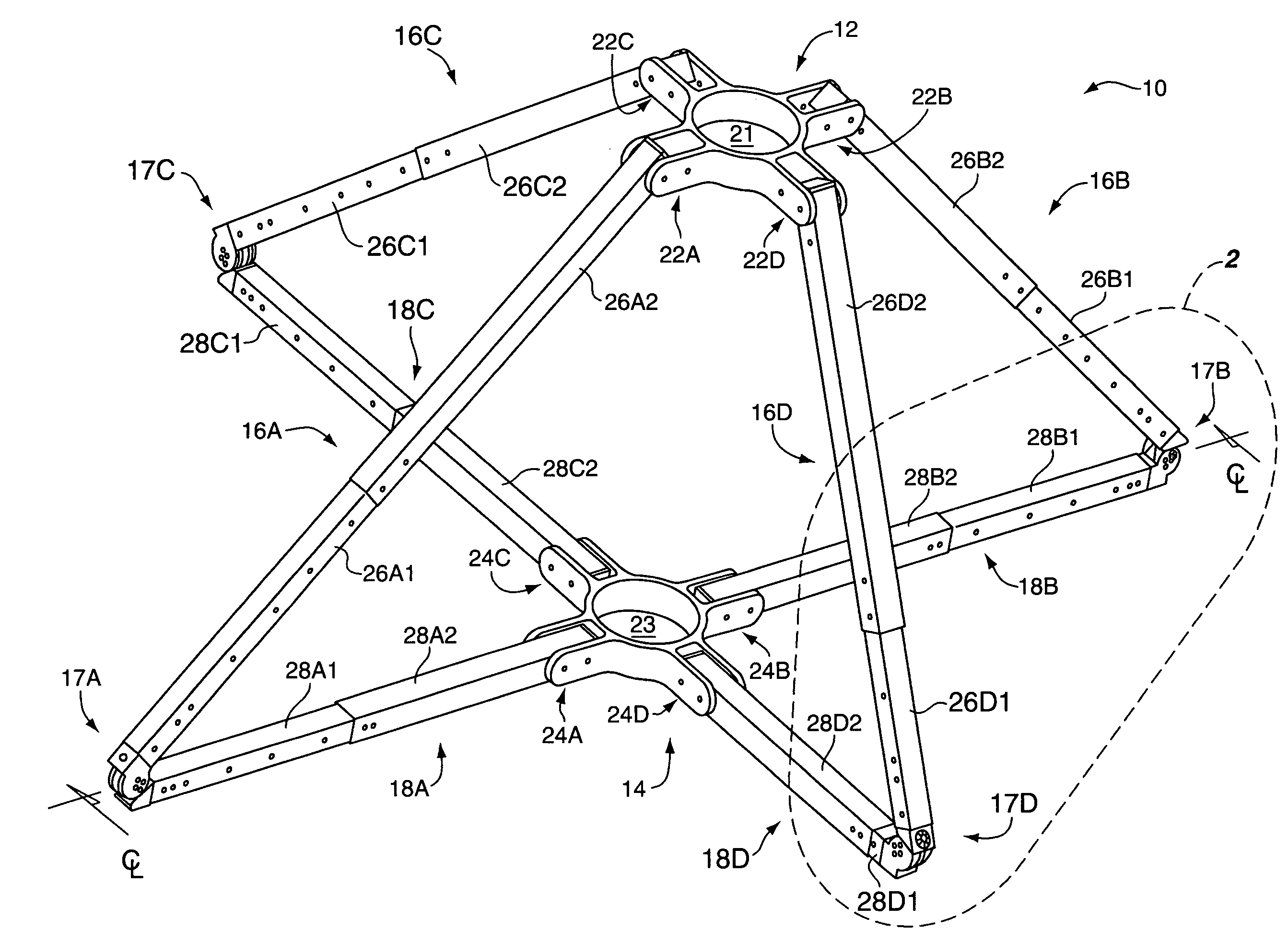
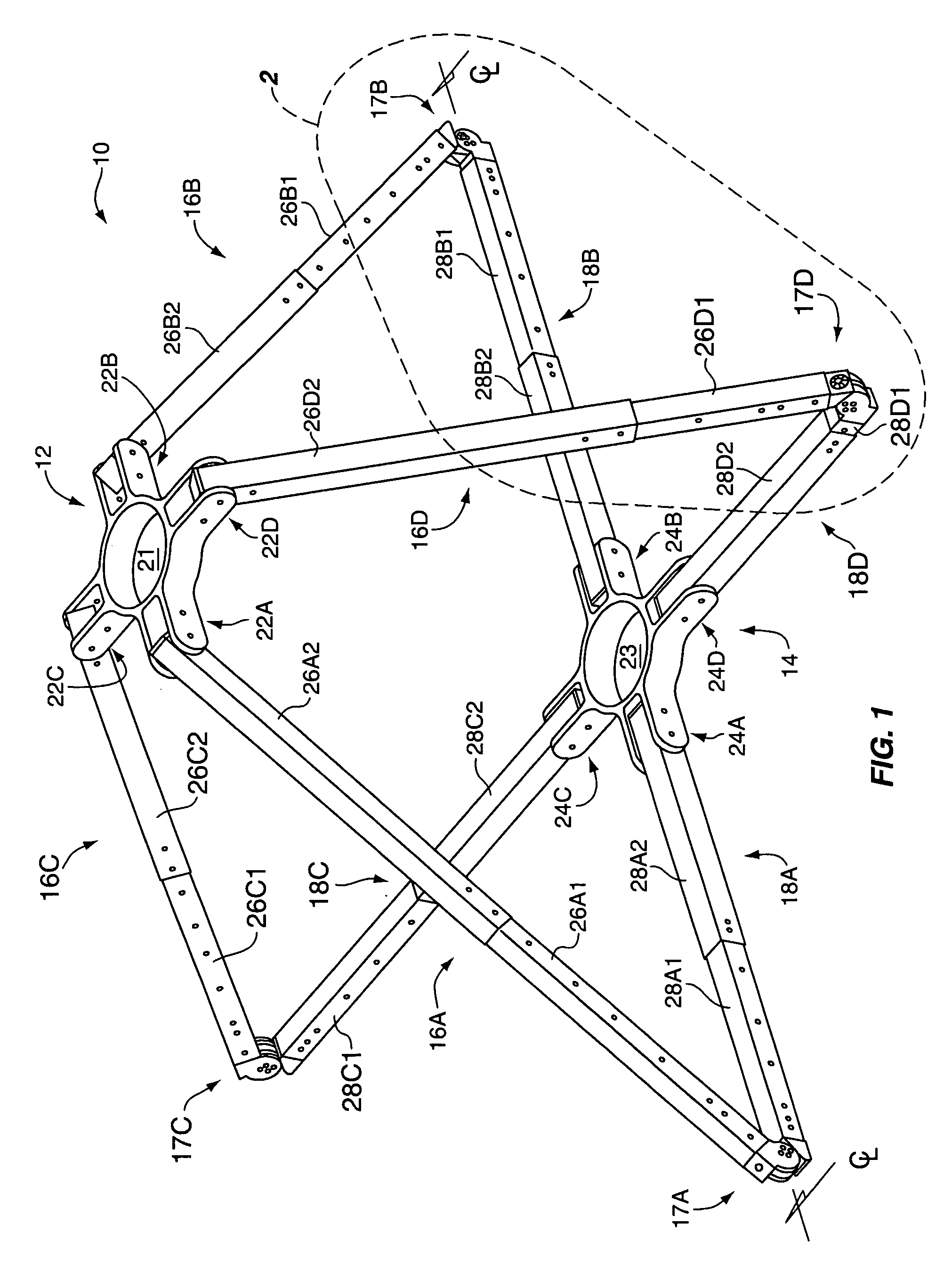
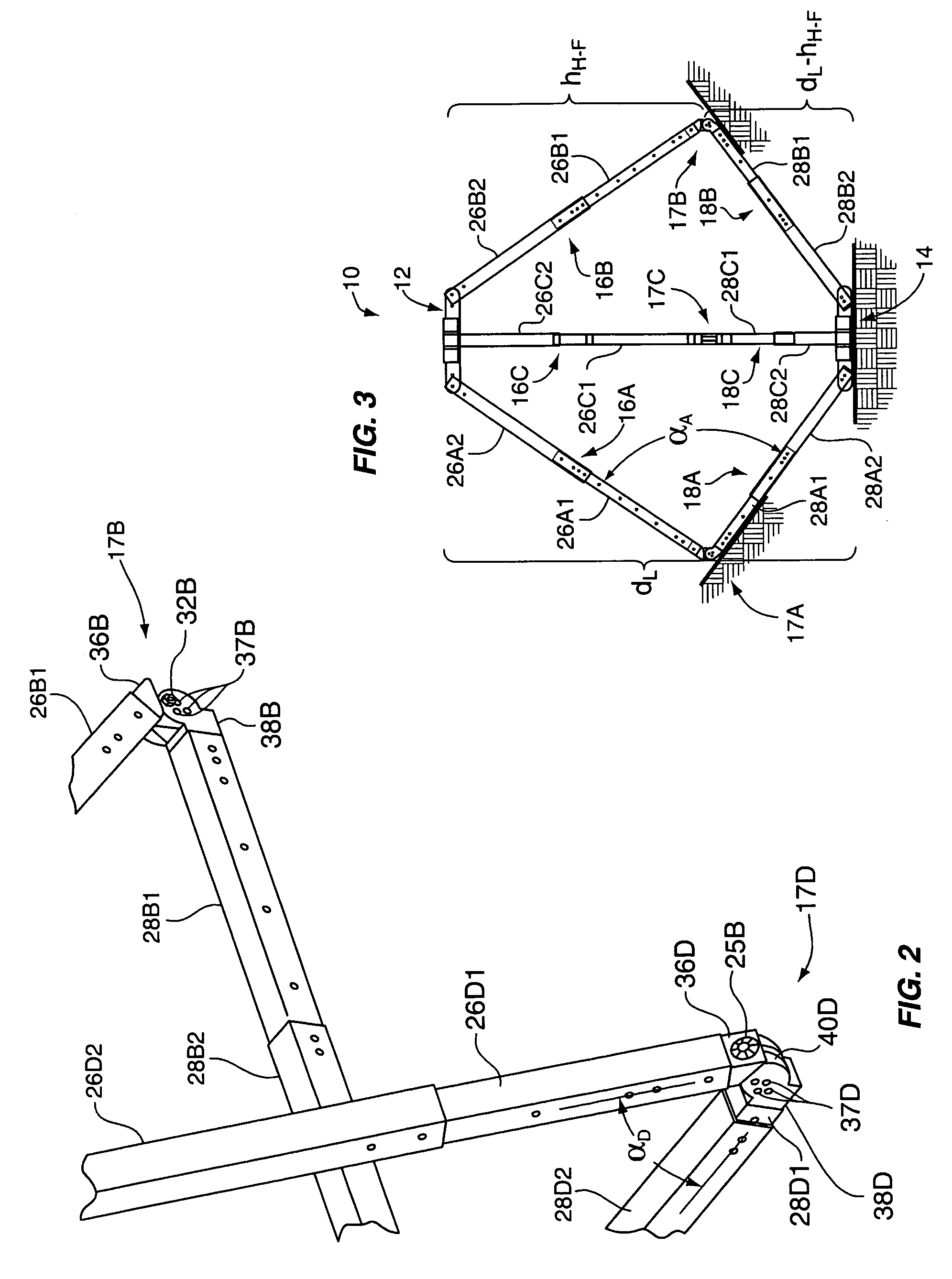
[0032]In connection with discussing the features in FIG. 1, occasional reference will be made back-and-forth to other of the figures, especially, FIGS. 2–8, 10–11, and 17, which detail core, as well as further unique and distinguishing features of an apparatus of the invention 10—and further providing a pictorial demonstration of the flexibility of design of applicant's invention. As one can appreciate, the configuration of the collapsible apparatus 10 in FIG. 1 is especially suitable for a ground surface(s) that is substantially planar; however, the configurations in FIGS. 3, 5A–5B, and 8 provide configurations of the apparatus 10 adaptable to uneven ground, including holes, divots, inclines / declines, and so on, of a variety of shapes and sizes.

[0033]As mentioned, the article can be of a myriad of shapes and sizes, and associated features of the apparatus will be accordingly sized and fabricated of material(s) having sufficient strength to support the article. While articles that a...


PUM


Abstract

A unique collapsible apparatus for supporting an article; the apparatus has at least a first, second, and third leg assembly, an upper end of each leg assembly pivotally secured to extend from an upper support member in a generally symmetrical fashion. A lower end of each leg assembly pivotally secured to extend from a lower support member (which may be in the shape of a collar). Each leg assembly has a unique hinge-fitting interconnecting a first and second elongated subassembly; a hinge-fitting may comprise a first and second extension pivotally enjoined. Each hinge-fitting permits a pivot range of rotation; preferably, this pivot range may be up to 90-degrees, up to 170-degrees, or just under 180-degrees. The elongated subassemblies may each be comprised of a plurality of telescoping tubular sections adapted for interlock. The telescoping tubular sections of an elongated subassembly may be sized for interchangeability with telescoping tubular sections of another elongated subassembly. Upper support member may have a plurality of fork extensions to which upper ends of the leg assemblies are pivotally secured. Upper support member may have an aperture for accepting an article, e.g., aperture will be sized to accept the periphery of the article. Lower collar support member may be adapted for accepting a lower-end of the article for placement on / in connection with a ground.

Description

[0001]This application claims the benefit of U.S. provisional patent application No. 60 / 419,599 filed 18 Oct. 2002 on behalf of the applicant hereof.BACKGROUND OF THE INVENTION[0002]In general, the present invention relates to portable support stands, such as those used for supporting a camera, survey equipment, telescope, holiday trees, as well as printed sheet music stands—all of which utilize multiple legs (most often in a tripod style) to support a specifically identified article for which the stand has been designed. While many of the current stand designs provide a certain basic amount of stability, each of these stands is quite limited in that each is designed to support the item for which it was specifically designed. Furthermore, most all of these traditional stand designs cannot be set up on ground that is not planar and level; few of these conventional designs provide much, if any, support when a gust of wind or inclement weather hits (heavy wind, rain, etc.); and in most...

Claims


Application Information

Patent Timeline
Patent Type & Authority Patents(United States)
IPC IPC(8): F16M13/00F16M11/38F16M11/00F16M11/20
CPCF16M11/00F16M11/046F16M11/20F16M11/2021F16M11/36F16M11/38F16M2200/028
Inventor WILLEY, KEVIN E.
Owner WILLEY KEVIN E
Why Eureka
Try Eureka