Rotary-type fastening structure

a fastening structure and rotary type technology, applied in the direction of rod connections, dismountable cabinets, couplings, etc., can solve the problems of short convenience of conventional structures and unsuitable for use in the industry

Inactive Publication Date: 2006-12-05
ENLIGHT
View PDF9 Cites 46 Cited by
  • Summary
  • Abstract
  • Description
  • Claims
  • Application Information

AI Technical Summary

Benefits of technology

[0003]In view of the foregoing drawbacks of the conventional structure, the present invention discloses a rotary-...

Problems solved by technology

Accordingly, the conventional structure is short of...

Method used


Image

  • Rotary-type fastening structure
  • Rotary-type fastening structure
  • Rotary-type fastening structure

Examples


Embodiment Construction

[0014]The above-mentioned features and advantages of this invention, and the manner of attaining them, will become more apparent and the invention will be better understood by reference to the following description of embodiments of the invention taken in conjunction with the drawings.

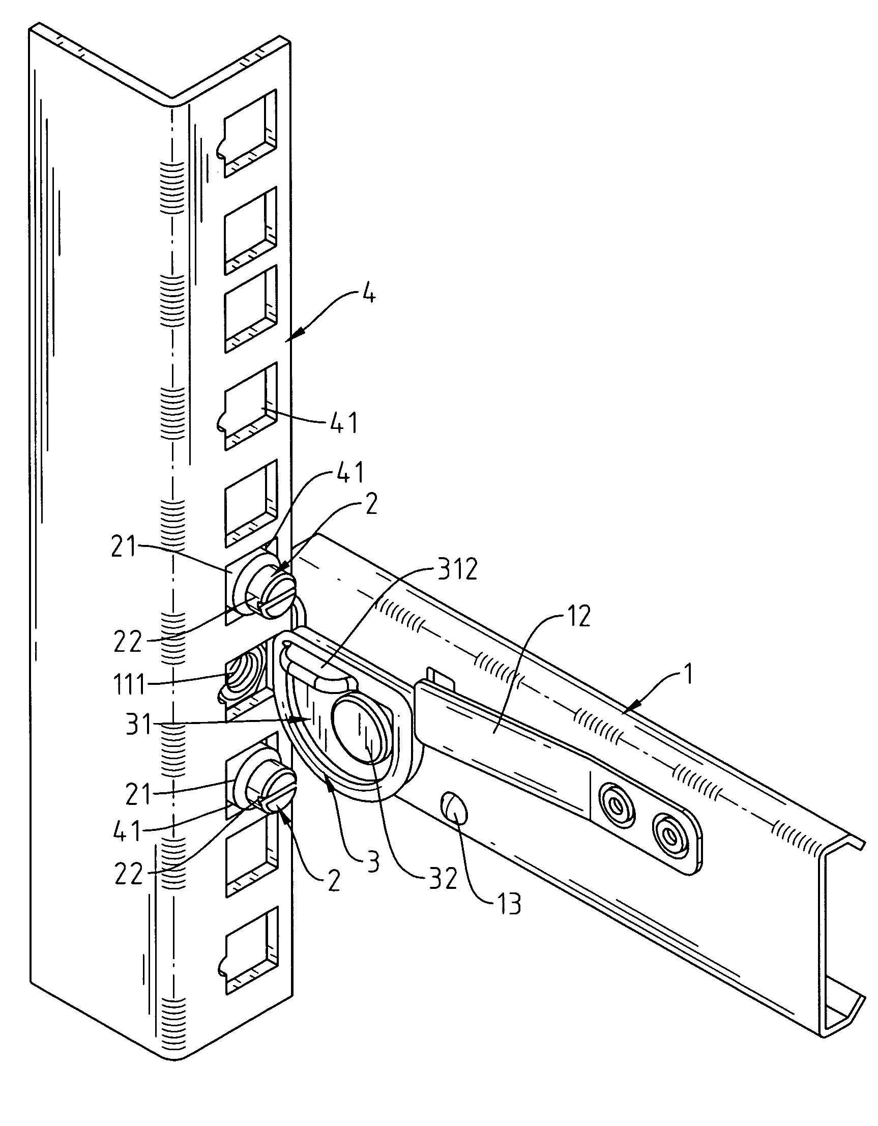
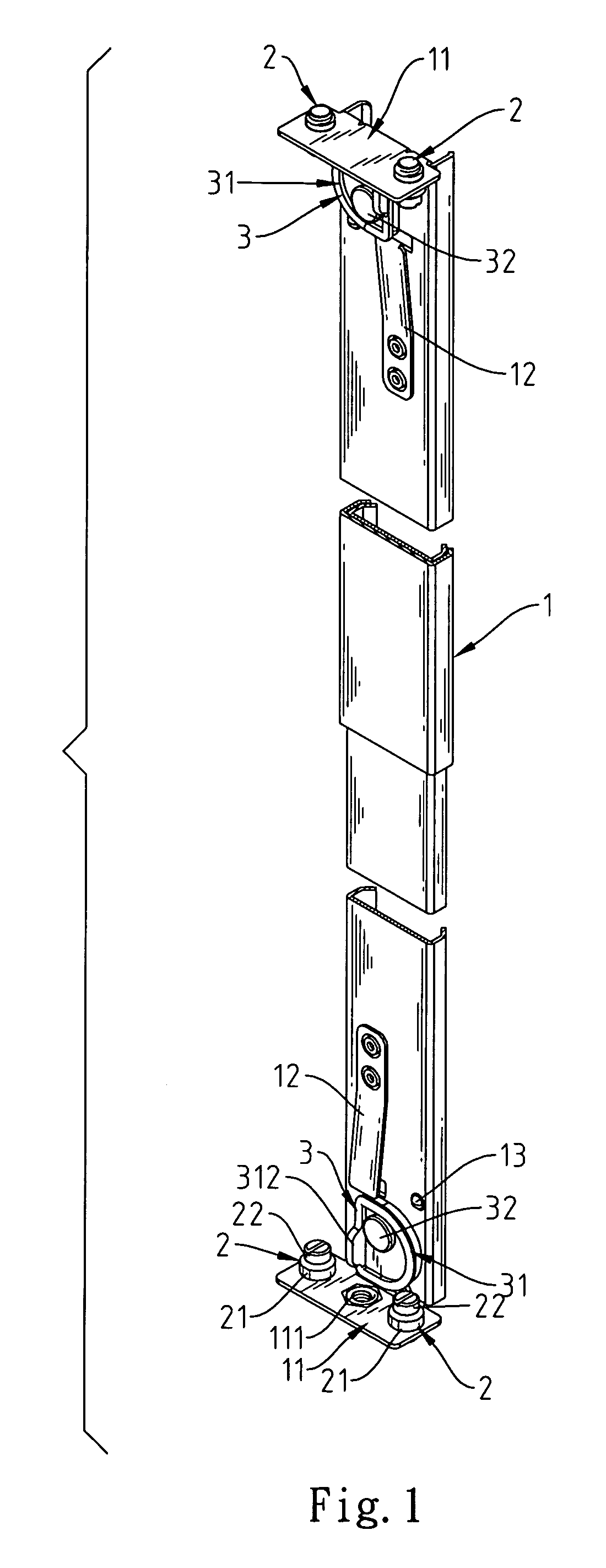
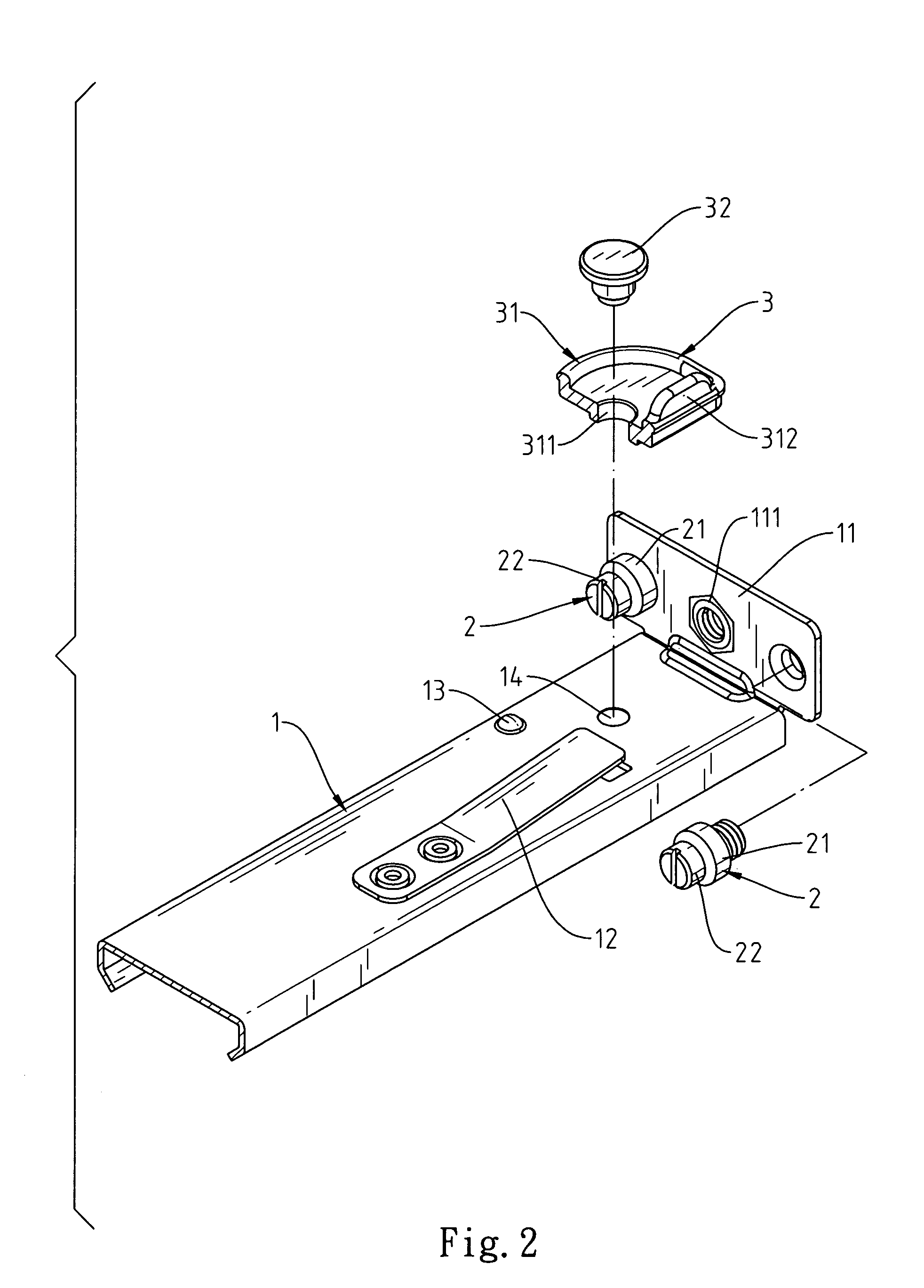
[0015]Referring to FIG. 1 through FIG. 3, a rotary-type fastening structure of the present invention is a structure for coupling an extension rod 1 with a coupling plate 4. In this preferred embodiment, two kinds of connection holes 41, 42 with different apertures are formed on the coupling plate 4 to adjust the method for locking the rotary-type fastening structure.

[0016]A lateral retaining plate 11 is mounted on each side of the extension rod 1, wherein one of these two lateral retaining plates 11 has a locking hole 111 on the center region for further fixing the extension rod 1 to the coupling plate 4. An elastic fastening sheet 12 is riveted on the extension rod 1 inside each of the lateral retaini...


PUM


Abstract

A rotary-type fastening structure for fixedly coupling an extension rod with a coupling plate, having a rotatable fastening device in the form of a main body with an off-center shaft hole. The rotatable fastening device can be rotated off-center so as to lean its lateral edge on the coupling plate and selectively secure the extension bar to the coupling plate.

Description

FIELD OF THE INVENTION[0001]The present invention is related to a rotary-type fastening structure for use in a slideway, and more particularly to an off-center rotary-type fastening structure with multi-stage locking devices.BACKGROUND OF THE INVENTION[0002]In the general server box, the aperture specification of the coupling plate coupled with the drawer slideway is fixed. The slideway is always coupled with the box or the lateral portion of the cabinet by a screwing method. As a result, the drawer or the tray can be coupled with the slideway for the push-pull purpose. However, different coupling plates are provided with different specifications. In order to be suitable for boxes of different specifications, the slideways of different specifications must be provided. Accordingly, the conventional structure is short of convenience and is not suitable for use in the industry.SUMMARY OF THE INVENTION[0003]In view of the foregoing drawbacks of the conventional structure, the present in...

Claims


Application Information

Patent Timeline
IPC IPC(8): F16B5/10A47B57/26
CPCA47B88/044F16B7/0486H05K7/1421F16B12/32F16B2/18Y10T403/7009Y10T403/33A47B88/43H05K7/1489
Inventor TSAI, SHIANG-SHIANG
Owner ENLIGHT
Why Eureka
Try Eureka