Sealed tamper resistant terminator

a terminator and seal technology, applied in the direction of coupling device details, coupling device connection, securing/insulating coupling contact members, etc., can solve the problems of corrosion of the internal components of the terminator, unauthorized removal of the terminator without the need for special tools, and the end of the equipment box being often exposed to the elements

Active Publication Date: 2006-12-05
PPC BROADBAND INC
View PDF20 Cites 117 Cited by
  • Summary
  • Abstract
  • Description
  • Claims
  • Application Information

AI Technical Summary

Benefits of technology

[0028]A further aspect of the present invention relates to a cap, preferably made from a resilient material, and adapted to selectively seal either a first end or a second end of a tamper resistant coaxial terminator of the type generally described above. The cap includes first and second opposing ends. The first end of the cap has a generally cylindrical first outer diameter commensurate with the internal diameter of the RF port of the terminator. In addition, the first end of the cap has an aperture formed therein for receiving the conductive center pin of the tamper resistant coaxial terminator as the first end of the cap is inserted into the first end of the tamper resistant coaxial terminator; this aperture is preferably bound

Problems solved by technology

Such circumstances might permit unauthorized persons to move a drop cable from one port to another port, diverting service from a paying subscriber to a non-paying user.
In addition, the terminals of the equipment box are often exposed to the elements.
Exposure to the elements, particularly moisture and rain, often results in corrosion of the internal components of the terminator.
The result is that the outer shell locks up with the internal components whereby the entire terminator assembly can then be rotated as a unit, allowing an unauthorized person to remove the terminator without the need for any specialized tools.
Prior efforts to secure and seal such terminators have not proven to be entirely satisfactory.
For example, some of such known terminators incorporate a relatively large number of components; the requirement for a relatively large number of parts, and related complex machining operations, cause the cost of production of such terminators to remain relatively high.
Other versions with reduced number of components are not secure

Method used


Image

  • Sealed tamper resistant terminator
  • Sealed tamper resistant terminator
  • Sealed tamper resistant terminator

Examples


Embodiment Construction

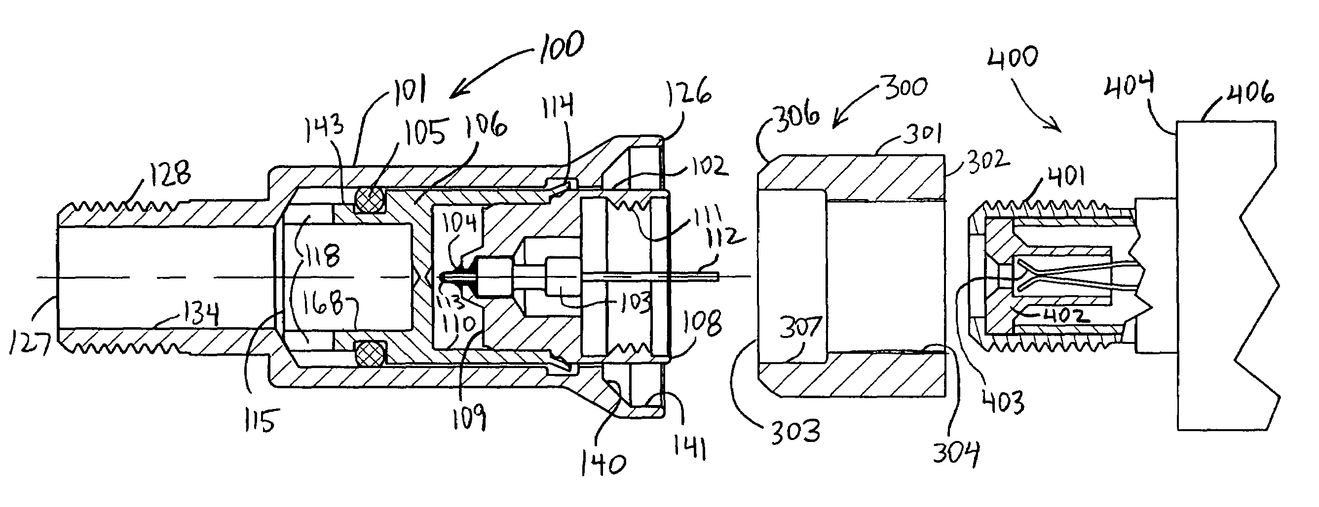
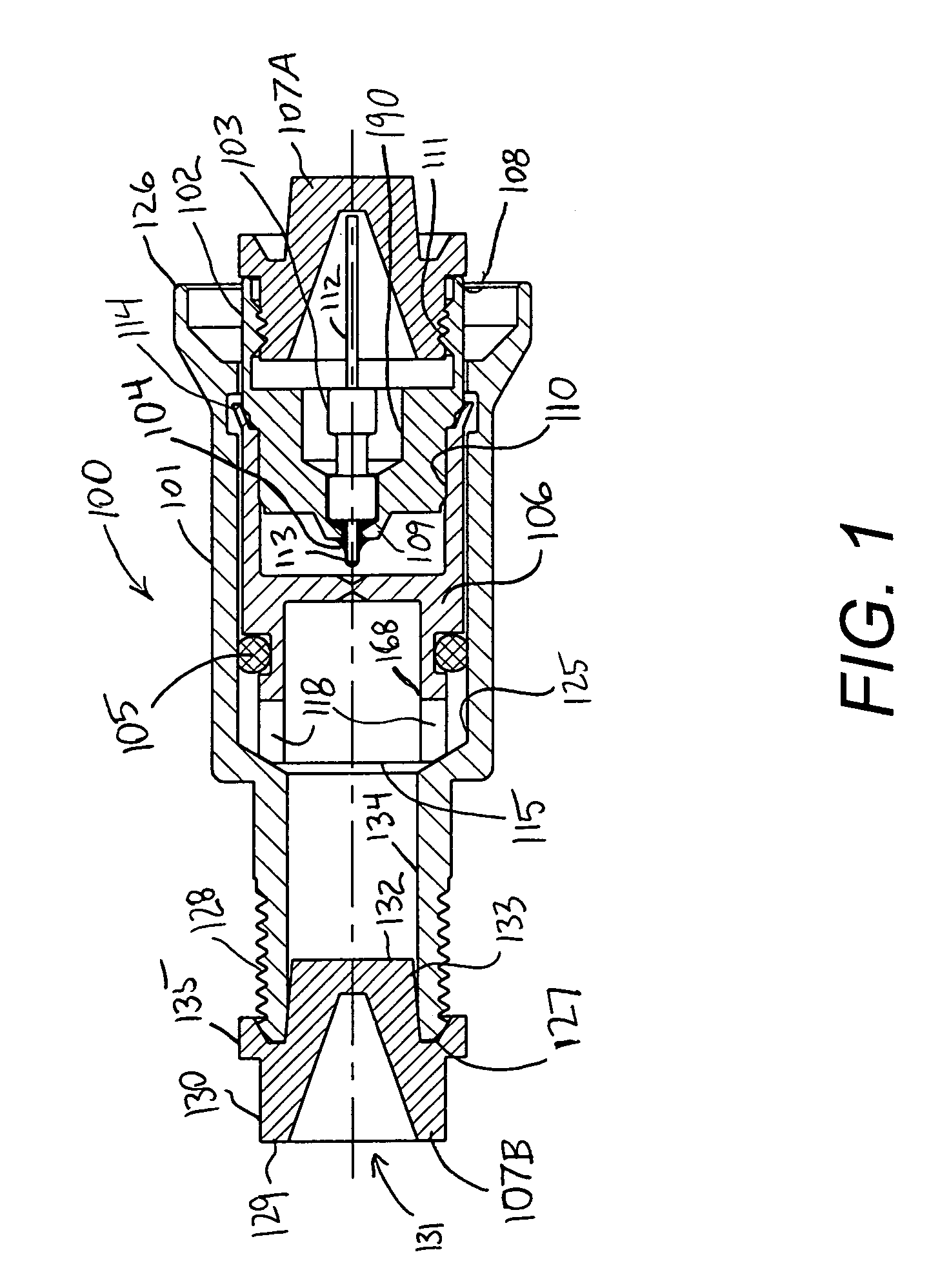
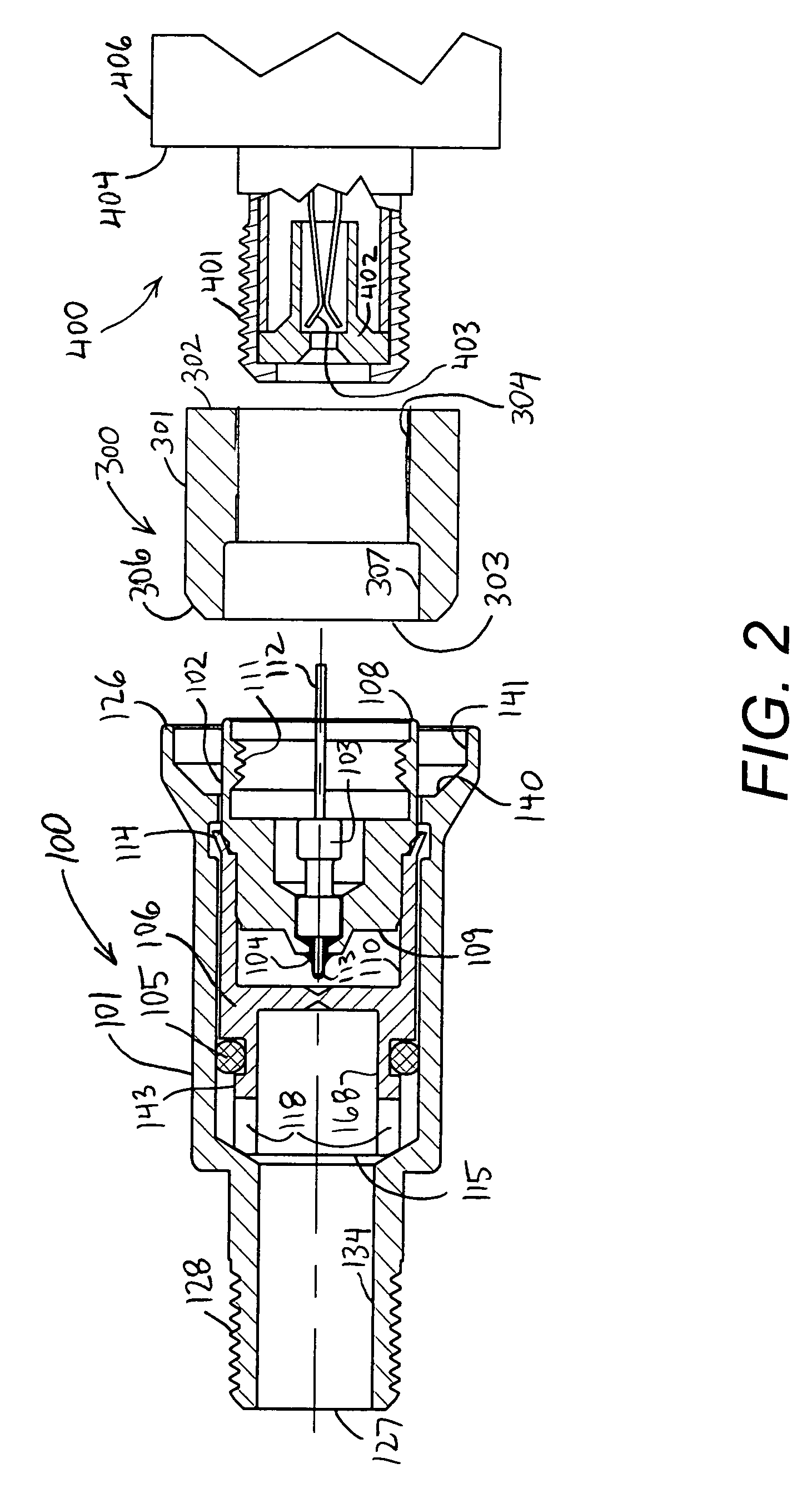
[0043]FIG. 1 illustrates a tamper resistant coaxial terminator for securing and terminating a coaxial equipment port of an equipment box, and constructed in accordance with a first embodiment of the present invention, along with a pair of end caps. The tamper resistant coaxial terminator 100 comprises an outer shield 101, an internally-threaded RF port 102, resistor 103, o-ring 105, inner body 106, and first and second seal plugs, or end caps, 107A and 107B. RF port 102 is made of electrically-conductive material, such as tin-plated brass, and extends between first and second opposing ends 108 and 109, respectively. First end 108 of RF port 102 has an inner surface defining a central bore 190 including an internally threaded region 111 for mating with the threads formed upon the outer conductor of a typical coaxial female equipment port, via rotation of RF port 102 relative to such equipment port.

[0044]Resistor 103 is housed within the central bore 190 of RF port 102 and extends bet...


PUM


Abstract

A tamper-resistant coaxial terminator includes an inner body rotatably captivated within an outer shield. A deformable portion of the inner body extends within an annular recess formed in the outer shield. An optional RF port, containing a resistor, is press-fit within the inner body. The RF port, or alternatively, the inner body, is internally-threaded for engaging the outer conductor of an equipment port. A seal ring extends over the outer conductor of the equipment port and is urged by the outer shield to directly engage the internally-threaded portion of the terminator. A seal is also optionally disposed between the outer shield and the inner body to minimize moisture induced corrosion. A shipping cap, usable at either end of the terminator, helps protect the terminator during shipment and prevents entry of debris.

Description

BACKGROUND OF THE INVENTION[0001]1. Field of the Invention[0002]The present invention relates generally to tamper resistant terminators and CATV coaxial connectors, and more particularly, to a tamper resistant terminator having an improved construction and sealing properties.[0003]2. Description of the Related Art[0004]Cable transmission systems are in wide use throughout the world for transferring television signals, and other types of signals, between devices. For example, a typical CATV system utilizes coaxial cables to provide signal communication between a head end and distributed receiver sets. A conventional CATV system includes a permanently installed cable extending from the head end throughout the area to be served. Various devices, such as directional taps, are spaced along the cable. Individual subscribers are serviced by a drop cable connected to a selected terminal of an equipment box or other device. The terminals that extend from the equipment box are externally thre...

Claims


Application Information

Patent Timeline
IPC IPC(8): H01R9/05
CPCH01R13/5219H01R13/6397H01R24/40H01R2103/00H01R2201/18
Inventor BURRIS, DONALD ANDREWKISLING, BRIAN L.LUTZ, WILLIAM B.
Owner PPC BROADBAND INC
Why Eureka
Try Eureka