Floor hinge assembly

a hinge assembly and floor technology, applied in the direction of hinges, wing accessories, manufacturing tools, etc., can solve the problems of reducing the ability of the hinge to rotate, the force between the pins and the edges of the guide slots is greatest, and the guide slots may experience a degree of wear that varies, so as to reduce the material weight and machining requirements, and reduce the potential for failure

Inactive Publication Date: 2008-06-05
BOMMER INDS
View PDF15 Cites 29 Cited by
  • Summary
  • Abstract
  • Description
  • Claims
  • Application Information

AI Technical Summary

Benefits of technology

[0005]The present invention provides advantages and alternatives over the prior art by providing a self-returning hinge assembly mounted between a support floor and a door utilizing a spring disposed along a linearly displaceable guide shaft element mounted through a guide plate aperture. Upon displacement of the door from a pre-established set point, the spring is compressed by a compression element carried by the guide shaft element thereby generating a biasing force along the guide shaft to bring the door back to the pre-established set point. The linear travel path of the guide shaft element is maintained by the guide plate without the need for the prior pin and guide slot engagement. Substantial reductions in material weight and machining requirements may thus be realized while simultaneously reducing the potential for failure due to interactive wear between the components.

Problems solved by technology

Moreover, it has been found that over extended periods of time, the guide slots may tend to experience a degree of wear that varies over the length of the slots.
This variable wear is believed to result from the fact that the pins are subject to increasing forces as each individual cycle progresses such that the force between the pins and the edges of the guide slots is greatest when the guide shaft has been fully extended and the spring is compressed.
This variable wear may give rise to a noticeable clicking sound over the life of the product.

Method used


Image

  • Floor hinge assembly
  • Floor hinge assembly
  • Floor hinge assembly

Examples


Embodiment Construction

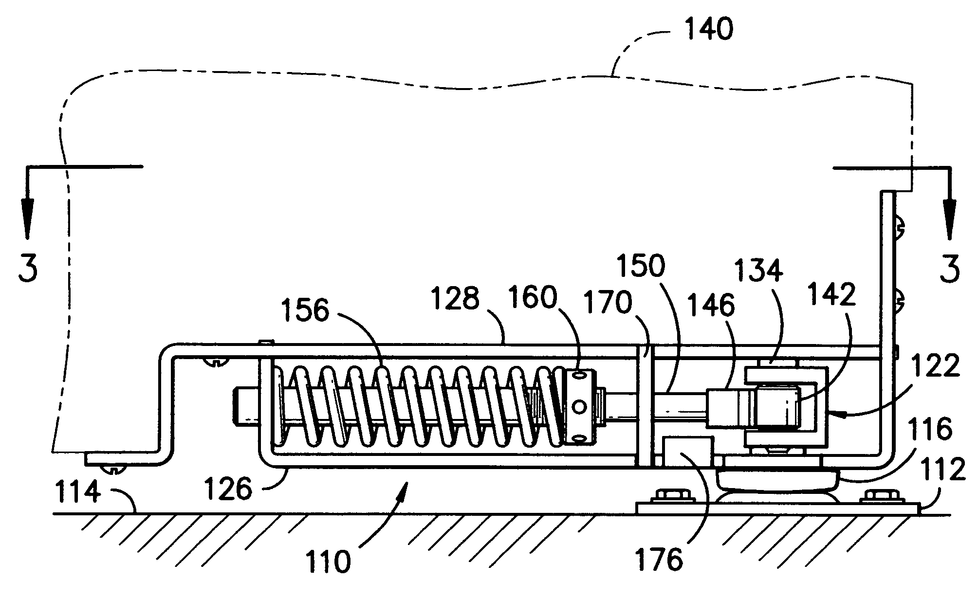
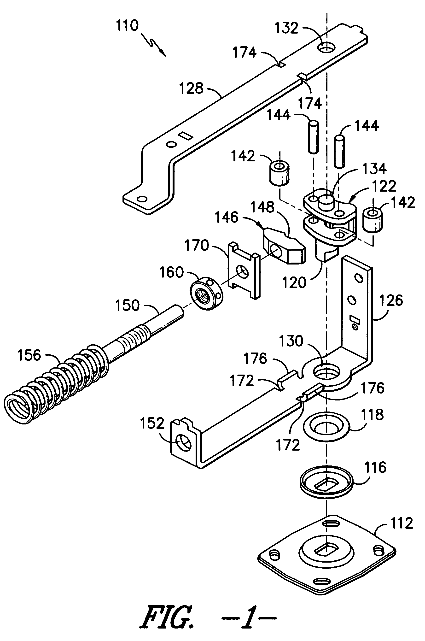
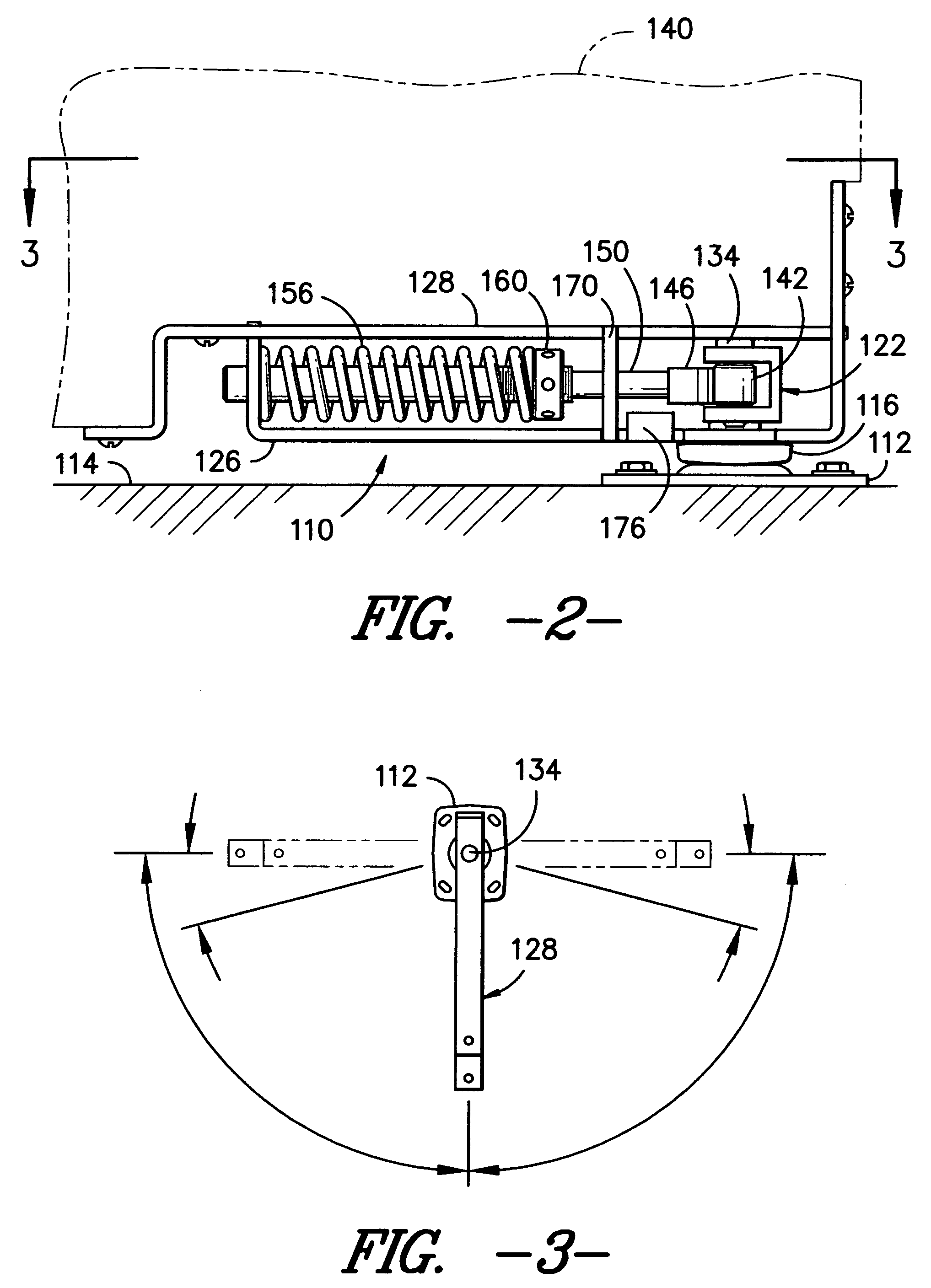
[0011]Reference will now be made to the drawings wherein, to the extent possible, like reference numerals are utilized to designate corresponding components throughout the various views. Looking now simultaneously to FIGS. 1 and 2, an exemplary hinge assembly 110 is illustrated. As shown, the hinge assembly 110 utilizes a base plate 112 mounted in substantially fixed relation to the floor 114 or other support surface. A bearing race 116 is secured to the base plate 112 and houses a bearing 118 such as a nylon ring bearing or the like. As shown, the base plate 112 and the bearing race include aligned key openings configured to accept a reduced diameter portion of a key post 120 projecting downwardly from a bearing cam assembly 122 as will be described further hereinafter. Thus, when the reduced diameter portion of a key post 120 projects through the aligned key openings, the bearing cam assembly 122 is held in fixed relation relative to the base plate 112.

[0012]In the illustrated con...


PUM


Abstract

An improved self returning floor mounted hinge assembly for a door. The hinge assembly includes a guide plate affixed to a support frame and having an opening substantially surrounding a linearly displaceable guide shaft. The opening in the guide plate is substantially aligned with an opening in the frame structure supporting the end of the guide shaft.

Description

TECHNICAL FIELD[0001]This invention relates to a self-returning hinge assembly mounted between a support floor and a door. More particularly, the invention relates to a self-returning hinge assembly mounted between a support floor and a door utilizing a spring disposed along a linearly displaceable guide shaft element mounted through a supporting guide plate element. Upon displacement of the door from a pre-established set point, the spring is compressed by a compression element carried by the guide shaft element thereby generating a biasing force along the guide shaft to bring the door back to the pre-established set point. The linear travel path of the guide shaft element is maintained by the guide plate. A construction method for the hinge assembly is also provided.BACKGROUND OF THE INVENTION[0002]Floor hinges are well known. As will be appreciated by those of skill in the art, such hinges typically use a base plate assembly that is bolted or otherwise mounted to the floor so as ...

Claims


Application Information

Patent Timeline
Patent Type & Authority Applications(United States)
IPC IPC(8): E05F3/20
CPCE05D3/08E05F1/1253Y10T16/304E05Y2900/132E05D7/081E05Y2600/10E05D15/54
Inventor JACKSON, B. STEWART
Owner BOMMER INDS
Why Eureka
Try Eureka