Micro lens and fabrication method of micro lens, optical device, optical transmitter, laser printer head, and laser printer

a technology which is applied in the field of micro lens and fabrication method of micro lens, can solve the problems of difficult control of the shape of the micro lens to form any desired shape, and difficulty in forming a micro lens of any arbitrary shape at any position, and achieve the effect of excelling in plotting characteristics

Inactive Publication Date: 2006-12-05
SEIKO EPSON CORP
View PDF29 Cites 179 Cited by
  • Summary
  • Abstract
  • Description
  • Claims
  • Application Information

AI Technical Summary

Benefits of technology

[0008]Further, simple use of the liquid droplet ejection method facilitated forming a micro lens at any position, but controlling its shape to form any desired shape was difficult.
[0029]According to the present laser printer, since it has a laser printer head having the proper plotting characteristics (optical characteristics) as mentioned above, the laser printer itself excels in plotting characteristics.

Problems solved by technology

However, the forming process using a die and photolithography requires a die and a complicated fabricating process to form a micro lens, and thus may be expensive.
Also, it is difficult to form a micro lens of any arbitrary shape at any position.
Further, simple use of the liquid droplet ejection method facilitated forming a micro lens at any position, but controlling its shape to form any desired shape was difficult.

Method used


Image

  • Micro lens and fabrication method of micro lens, optical device, optical transmitter, laser printer head, and laser printer
  • Micro lens and fabrication method of micro lens, optical device, optical transmitter, laser printer head, and laser printer
  • Micro lens and fabrication method of micro lens, optical device, optical transmitter, laser printer head, and laser printer

Examples


Embodiment Construction

[0042]Exemplary embodiments of the present invention will be described below with reference to the drawings.

Micro Lens

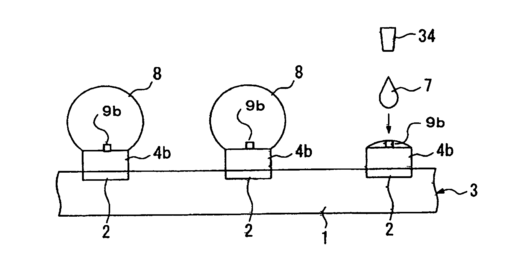
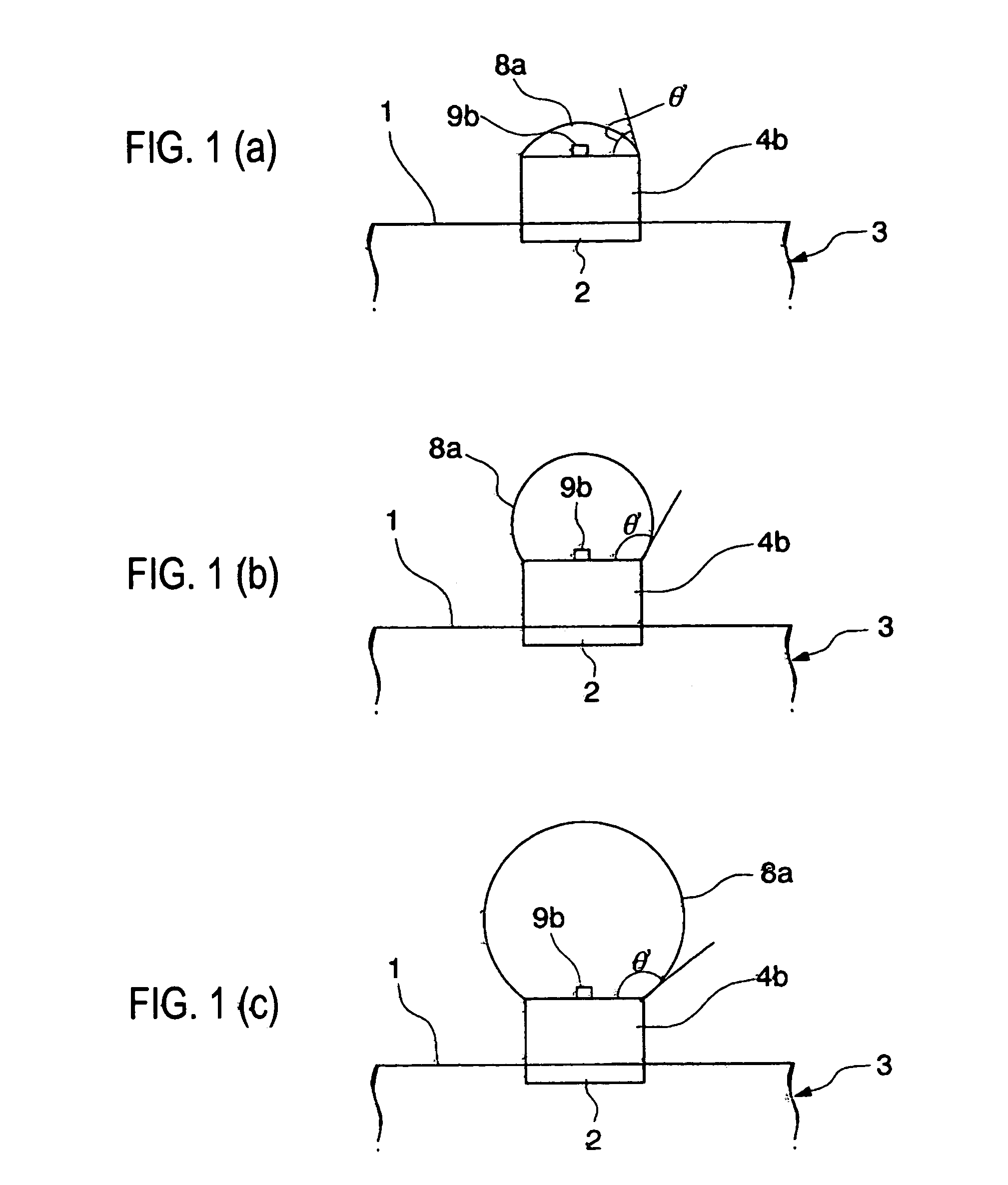
[0043]FIGS. 1(a)–1(c) show a micro lens of an exemplary embodiment according to the present invention, showing cross-sectional views of a principal part of a lens member 8a of various shapes. In FIGS. 1(a) to (c) are shown various shapes of the lens member, that is, a flat shape (FIG. 1(a)) through a shape whose side is close to a semi-sphere (FIG. 1(b)) to a shape whose side is close to a sphere (FIG. 1(c)).

[0044]In FIGS. 1(a) to (c), a substrate 3 has a surface capable of forming a base member 4b, specifically, a glass substrate, a semiconductor substrate, and further that which is formed of various functional thin films and functional elements. Also, as for the surface that can form the base member 4b, it may be a plane or a curved surface. Further, as for the shape of the substrate 3 itself, it is not limited to any particular shape, but various shapes may be ado...


PUM

PropertyMeasurementUnit
contact angleaaaaaaaaaa
surface tensionaaaaaaaaaa

Abstract

A micro lens is provided with proper optical characteristics, such as a condensing function. Furthermore, a fabrication method of a micro lens is provided as well as, an optical device, an optical transmitter, a laser printer head, and a laser printer. The micro lens is equipped with a lens member formed by a liquid droplet ejection method, including: a base member formed on a substrate, a lens member formed on an upper surface of the above-mentioned base member to which the lens material is ejected in a plurality of dots by the liquid droplet ejection method, the upper surface of the base member having a concavity and a convexity with at least a part of the upper surface of the base member being subjected to repellant treatment.

Description

BACKGROUND OF THE INVENTION[0001]1. Field of Invention[0002]Exemplary aspects of the present invention relate to a micro lens and a fabrication method of a micro lens, and an optical device equipped with the micro lens, an optical transmitter, a laser printer head, and a laser printer.[0003]2. Description of Related Art[0004]Related art optical devices having a large number of minute lenses are called micro lenses. Such optical devices include, for example, a light-emitting device equipped with a laser, an optical interconnection of optical fibers, and further a solid imaging device having a condenser lens to condense incident light.[0005]A micro lens constituting such an optical device can be formed by a forming process using a die and photolithography. See Japanese Unexamined Patent Publication No. 2000-35504.[0006]Also, a liquid droplet ejection method being employed for a printer and the like may be used to form a micro lens in a minute pattern. See Japanese Unexamined Patent Pu...

Claims


Application Information

Patent Timeline
Patent Type & Authority Patents(United States)
IPC IPC(8): G02B27/10B29D11/00B32B17/06B41J2/015B41J23/00B41J2/44G02B3/00
CPCG02B3/00G03G15/04072G03G2215/0404B29D11/00
Inventor HASEI, HIRONORIKITO, SATOSHI
Owner SEIKO EPSON CORP
Why Eureka
Try Eureka