Caster for vacuum cleaner and vacuum cleaner having the same

Inactive Publication Date: 2006-12-12
LG ELECTRONICS INC
View PDF13 Cites 2 Cited by
  • Summary
  • Abstract
  • Description
  • Claims
  • Application Information

AI Technical Summary

Benefits of technology

[0016]The vacuum cleaner of the present invention can be stably supported in the state where the main body of the vacuum clea

Problems solved by technology

However, according to the conventional vacuum cleaner constructed as such, there is inconvenience as follows.
However, since the conventional caster roller 14 is constructed to be rotatable and has an insufficient length in a right and left direction, there is a difficulty in supporting the main body of the vacuum cleaner in the state where it is put over the stairs.
Therefore, it is substantially im

Method used


Image

  • Caster for vacuum cleaner and vacuum cleaner having the same
  • Caster for vacuum cleaner and vacuum cleaner having the same
  • Caster for vacuum cleaner and vacuum cleaner having the same

Examples


Example

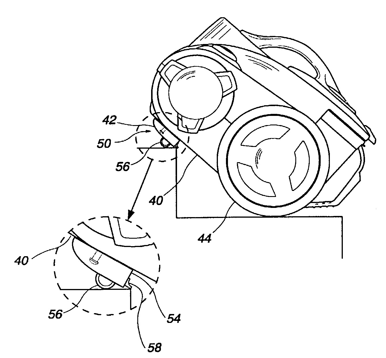
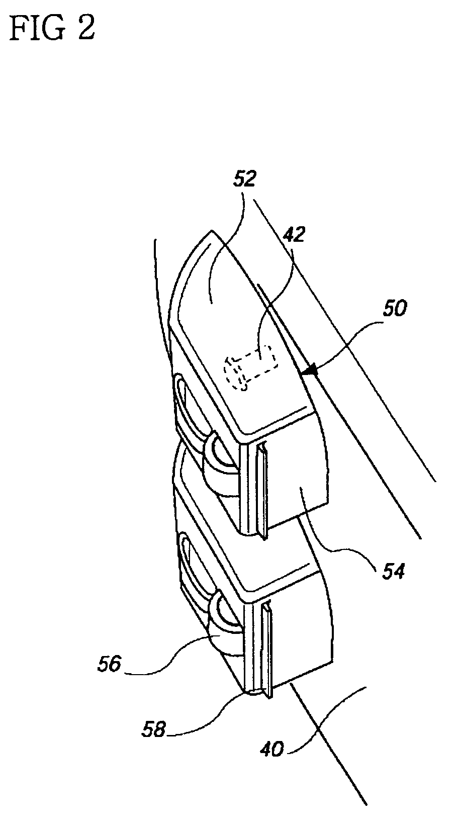
[0022]Hereinafter, the present invention will be described in detail with reference to a preferred embodiment shown in the accompanying drawings. FIGS. 2 and 3 are perspective views showing a bottom surface of a main body of a vacuum cleaner according to the present invention. As shown in these figures, a caster 50 is installed to be rotatably supported at a front portion of the bottom surface 40 of the main body of the vacuum cleaner. It will be apparent that the vacuum cleaner of the present invention includes a suction power generating means capable of generating suction power therein, specifically a motor capable of generating vacuum within the main body of the vacuum cleaner.

[0023]In the illustrated embodiment, it can be seen that the caster 50 is in pairs in a right and left direction. Each caster 50 is installed to be supported rotatably on a horizontal plane so that a travel direction of the vacuum cleaner can be more smoothly changed when traveling on a floor surface.

[0024]...


PUM


Abstract

A caster structure for a vacuum cleaner is provided which allows the main body of the vacuum cleaner to be stably positioned at an incline. The caster structure is rotatably supported on a front portion of a bottom surface of the main body of the vacuum cleaner, and includes a caster body which has a planar rear surface, and a caster roller rotatably installed in the caster body 52. The planar rear surface of the caster body includes a slip-prevention protrusion which extends across the planar rear surface to prevent slippage of the main body of the vacuum cleaner when the main body is positioned at an incline. The caster structure may include a single caster, or a pair of casters positioned side by side on the bottom surface of the main body of the vacuum cleaner.

Description

BACKGROUND OF THE INVENTION[0001]1. Field of the Invention[0002]The present invention relates to a vacuum cleaner, and more particularly, to a caster for a vacuum cleaner, which is constructed such that a travel direction of the vacuum cleaner can be changed when traveling on a surface to be cleaned and a main body of the vacuum cleaner can be maintained in a state where it is put over stairs.[0003]2. Description of the Prior Art[0004]Referring first to FIG. 1, the entire constitution of a conventional vacuum cleaner will be described. The vacuum cleaner comprises a main body 2 with a motor contained therein for generating suction power, a connecting hose 4 that is made of a flexible material and communicates with the interior of the main body 2, an extension tube 6 connected to the connecting hose 4 and constructed such that the length of the tube can be adjusted, and a suction nozzle 8 installed at an end of the extension tube 6 to suck air containing foreign substances from a flo...

Claims


Application Information

Patent Timeline
IPC IPC(8): A47L9/00A47L5/36
CPCA47L5/362A47L5/367A47L9/009A47L9/00
Inventor KIM, SUNG-GUEN
Owner LG ELECTRONICS INC
Why Eureka
Try Eureka