Vacuum cleaner and suction nozzle structure thereof

Inactive Publication Date: 2006-03-02
LG ELECTRONICS INC
View PDF15 Cites 17 Cited by
  • Summary
  • Abstract
  • Description
  • Claims
  • Application Information

AI Technical Summary

Benefits of technology

[0017] By using the supposed configuration, the suction nozzle may be handled in an easier way, and inside of the suction nozzle may be cleaned in a m

Problems solved by technology

Meanwhile, the upright vacuum cleaner has a limitation in cleaning the whole indoor space due to its own shape.
For example, the main nozzle of the upright vacuum cleaner cannot reach a corner or an edge of such as a stairway, the corner or edge cannot be cleaned.
However, this method of combining the upper and lower covers by a screw is inconvenient for repairing or cleaning inside of the mini nozzle since a user cannot watch the inside of the mini nozzle until it is dissembled.
In addition, in order to prepare a separate space for forming

Method used


Image

  • Vacuum cleaner and suction nozzle structure thereof
  • Vacuum cleaner and suction nozzle structure thereof
  • Vacuum cleaner and suction nozzle structure thereof

Examples


Example

[0027] Reference will now be made in detail to the preferred embodiments of the present invention, examples of which are illustrated in the accompanying drawings. However, the spirit of the invention is not limited to the embodiments, but those skilled in the art might easily propose other embodiments by adding, changing, deleting or modifying components within the scope of the invention.

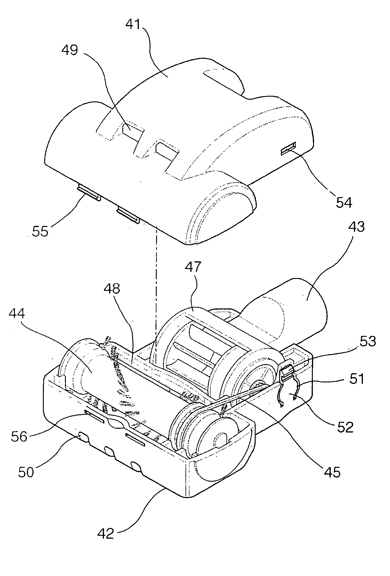
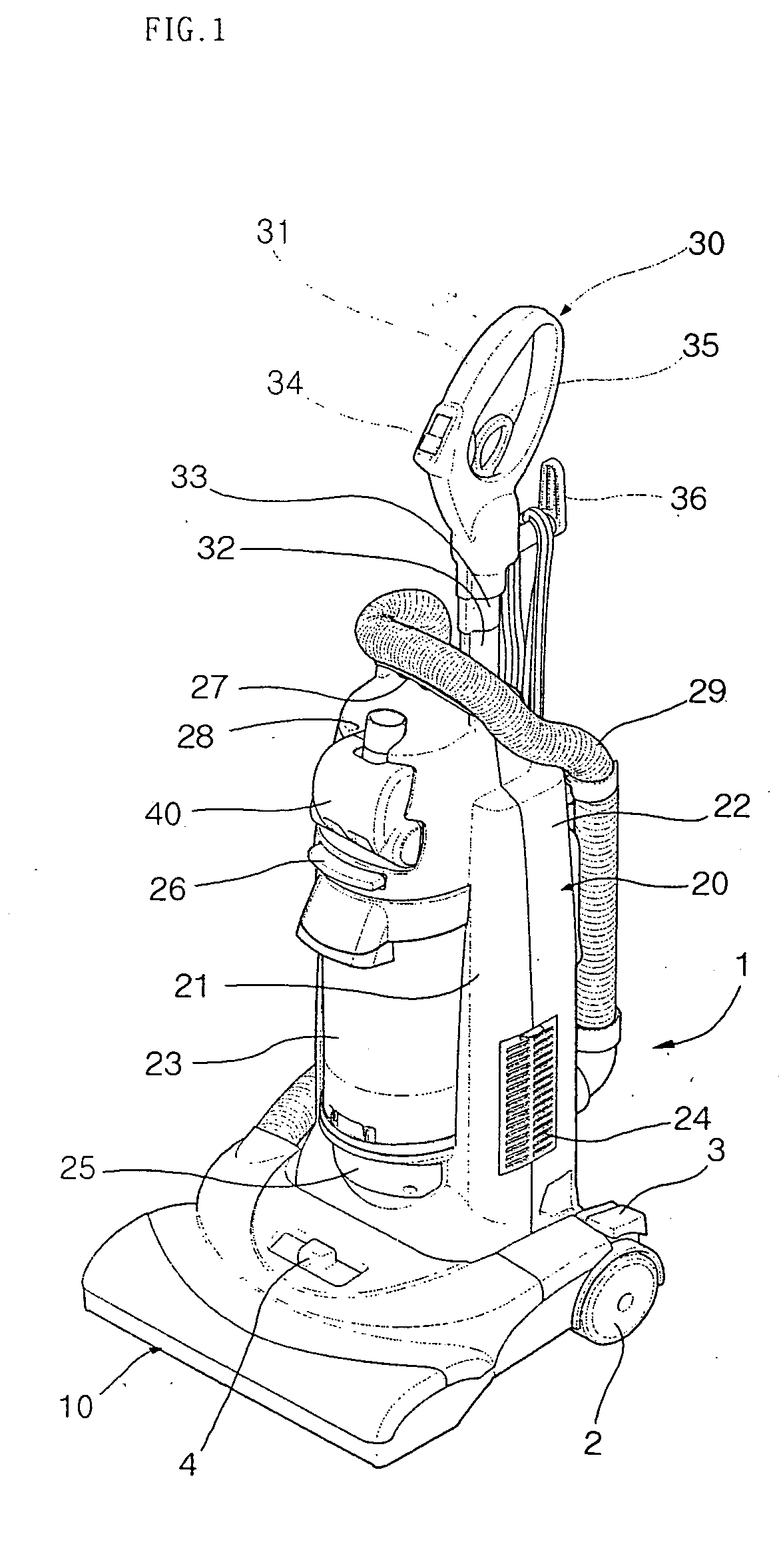
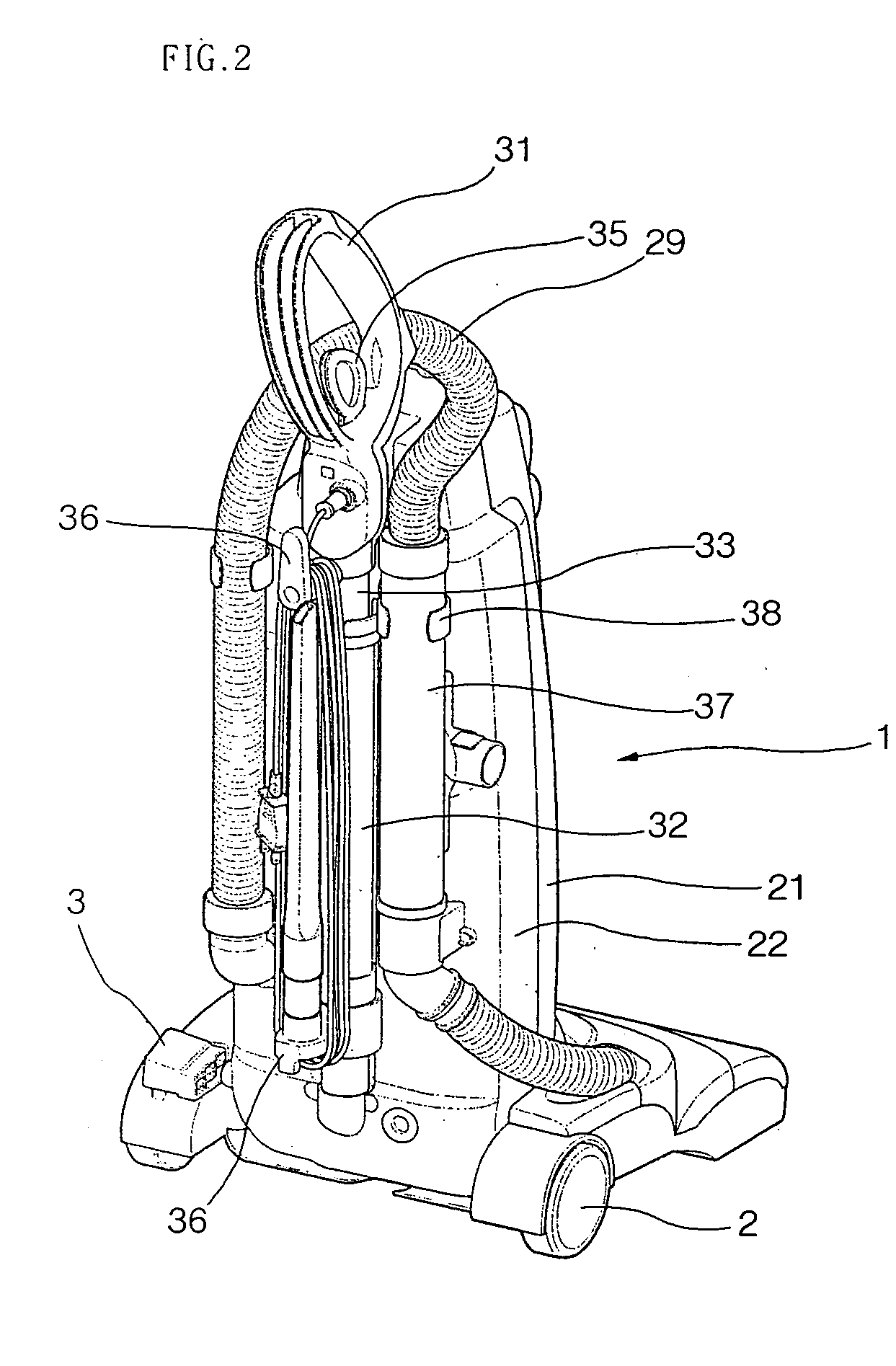
[0028]FIG. 1 is a front perspective view of an upright vacuum cleaner according to the present invention, and FIG. 2 is a rear perspective view of the upright vacuum.

[0029] Referring to FIGS. 1 and 2, the upright vacuum cleaner 1 of the present invention macroscopically includes a suction nozzle unit 10 contacted with a floor, for sucking an outer air, a body 20 in which main parts such as a suction motor and a fan are mounted, and a manipulation handle 30 formed on an upper portion of the vacuum cleaner such that the vacuum cleaner is moved in an easy way during the cleaning work. The cleaning wo...


PUM


Abstract

Provided is a mini nozzle protected by upper and lower covers, the upper and lower covers being combined by hooking so that a user may handle conveniently.

Description

BACKGROUND OF THE INVENTION [0001] 1. Field of the Invention [0002] The present invention relates to a vacuum cleaner, and particularly to a suction nozzle of the vacuum cleaner that gives improved convenience in use. More particularly, the present invention relates to a suction nozzle structure of an upright vacuum cleaner that allows a user to clean inside of a mini nozzle conveniently and to assemble and dissemble the mini nozzle in a simple way by improving structure of the mini nozzle used for cleaning a corner which is not contacted with a main body of the vacuum cleaner. [0003] 2. Description of the Related Art [0004] A vacuum cleaner is generally classified into a canister vacuum cleaner and an upright vacuum cleaner. Particularly, the upright vacuum cleaner includes a main body, a nozzle unit and a handle that are integrally formed, so the vacuum cleaner itself is moved when a user pushes or pulls a handle with gripping it. At this time, dusts on the floor are sucked throug...

Claims


Application Information

Patent Timeline
IPC IPC(8): A47L5/00A47L9/00
CPCA47L5/32A47L9/0009A47L9/0416A47L9/0045A47L9/0036A47L9/02
Inventor KIM, KYUNG CHUL
Owner LG ELECTRONICS INC
Why Eureka
Try Eureka