Device and method for multi-phase radio-frequency ablation

Inactive Publication Date: 2006-12-19
MORVIL TECH LLC
View PDF10 Cites 175 Cited by
  • Summary
  • Abstract
  • Description
  • Claims
  • Application Information

AI Technical Summary

Benefits of technology

[0023]In one embodiment, each electrode is supplied with an RF source having a different phase. In this way, potential differences are created between each pair of electrodes in the array, thereby allowing current to flow between each pair of electrodes in the array to form a more uniform heating pattern therein.
[0024]In another embodiment, a simplified power connection configuration provides a phase difference between at least adjacent pairs of electrodes. In this way, potential differences are created between at least adjacent pairs of electrodes in the array, thereby allowing current to flow between each adjacent pair in the array to form a more uniform heating pattern therein.
[0025]One important aspe

Problems solved by technology

Another common type of cardiac dysrhythmias is ventricular tachycardia (VT), which is a complication of a heart attack or reduction of blood supply to an area of heart muscle, and is a life threatening arrhythmia.
However, some dysrhythmias of the heart are not treatable with drugs.
Both procedures have increased morbidity and mortality and are extremely expensive.
In addition, some patients of advanced age or illness cannot tolerate invasive surgery to excise tachycardia focus which causes dysrhythmias.
Additionally, high voltage tec

Method used


Image

  • Device and method for multi-phase radio-frequency ablation
  • Device and method for multi-phase radio-frequency ablation
  • Device and method for multi-phase radio-frequency ablation

Examples


Embodiment Construction

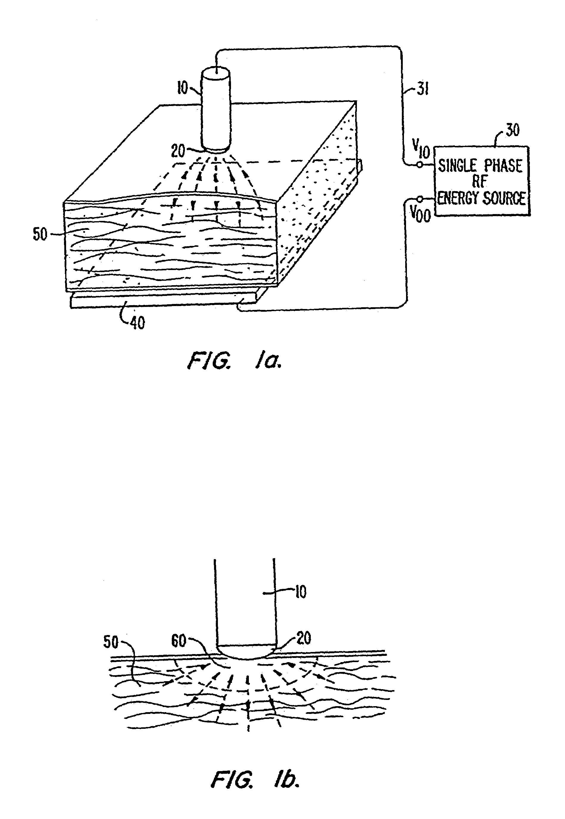
[0060]FIG. 1a illustrates the conventional technique of single-phase radio-frequency (SPRF) ablation employing a standard electrode catheter 10. An electrode 20 is located at the tip of the catheter and is electrically connected to a single-phase RF energy source or power supply 30. The other end of the power supply 30 is connected to a backplate 40. The electrode 20 is typically hemispheric in shape with a diameter of not more than 0.3 mm so as to allow easy insertion into a patient's body. During operations, the electrode 20 is placed adjacent a region to be ablated such as biological tissues 50 inside a heart (endomyocardium). A closed circuit is formed with the backplate 40 in contact with an external body part near the heart of the patient. RF current spreads perpendicularly from the electrode catheter 20 to the backplate 40 creating a lesion on the endomyocardium 50.

[0061]FIG. 1b illustrates in more detail the ablation region shown in FIG. 1a. Since the RF current density is h...


PUM


Abstract

Multi-phase RF ablation employing a two-dimensional or three-dimensional electrode array produces a multitude of currents paths on the surface of the ablation zone. This results in a uniform lesion with a size defined by the span of the electrode array. An orthogonal electrode catheter array suitable for cardiac ablation is used in conjunction with a two-phase RF power source to produce uniform square-shaped lesions of size 1.2 cm2. Lesions of larger size are created by successive adjacent placement of the square-shaped lesions. A temperature sensor at the electrode tip allows monitoring of ablation temperature and regulation of thereof to minimize the electrode tips from being fouled by coagulum. In another embodiment, an external auxiliary electrode is used in combination with the catheter electrodes. This also produces lesions of greater depth. In yet another embodiment, ablation is performed with a sequence of elementary electrode-electrical configurations.

Description

[0001]This application is a continuation of U.S. Ser. No, 09 / 922,128, now abandoned filed Aug. 3, 2001, which is a continuation of U.S. Ser. No. 09 / 405,733, filed Sep. 24, 1999, now abandoned which is a Continuation-in-Part of Application Ser. No. 08 / 318,427, filed Oct. 5, 1994, now U.S. Pat. No. 5,693,078, which is a continuation of U.S. Ser. No. 07 / 726,035, filed Jul. 5, 1991, now U.S. Pat. No. 5,383,917.BACKGROUND OF THE INVENTION[0002]This invention relates to medical devices and, in particular, a multi-electrode catheter and techniques therefor of employing multi-phase radio-frequency power source for ablation of endocardiac tissues.[0003]Cardiac dysrhythmias are commonly known as irregular heart beats or racing heart. Two such heart rhythm irregularities are the Wolff-Parkinson-White syndrome and atrioventricular (AV) nodal reentrant tachycardia. These conditions are caused by an extraneous strand of muscle fiber in the heart that provides an abnormal short-circuit pathway for...

Claims


Application Information

Patent Timeline
IPC IPC(8): A61N1/05A61B18/00A61B18/12A61B18/14A61N1/06A61N1/40
CPCA61N1/06A61N1/403A61B18/12A61B18/1206A61B18/1492A61B2018/0075A61B2018/00767A61B2018/00779A61B2018/00791A61B2018/00839A61B2018/00869A61B2018/124A61B2018/1273A61B2018/1467A61B2018/00041A61B2018/0016A61B2018/00351A61B2018/00357A61B2018/00577A61B2018/0066
Inventor DESAI, JAWAHAR M.NYO, HTAY L.
Owner MORVIL TECH LLC
Why Eureka
Try Eureka