Power connector dedicated to heating film

一种电源接头、电热膜的技术,应用在电热装置、欧姆电阻加热、欧姆电阻加热零部件等方向,能够解决火灾危险性变高、裸线突出、危险等问题,达到节省施工工作量、节省成本、简单电源连接的效果

Inactive Publication Date: 2019-11-26
SH KOREA CO LTD
View PDF13 Cites 0 Cited by
  • Summary
  • Abstract
  • Description
  • Claims
  • Application Information

AI Technical Summary

Problems solved by technology

[0006] If the prior art method as mentioned above is adopted, when the connector for supplying power to the electrothermal film protrudes from the floor, it will cause a problem of unsightly appearance due to the protrusion on the plane after the construction is completed, and further cause the problem of implementing the electrothermal film The problem of inconvenient maintenance and maintenance of the floor after construction
[0007] In addition, when the connection between the electrothermal film and the power supply adopts such as Figure 16 Any construction method shown (B-1: front, B-2: back) may cause danger due to protruding bare wires, and may cause heat generation due to poor contact at the contact part through which high current flows. phenomenon and consequently lead to the problem of increased fire hazard

Method used


Image

  • Power connector dedicated to heating film
  • Power connector dedicated to heating film
  • Power connector dedicated to heating film

Examples


Embodiment Construction

[0031] Next, the present invention will be described with reference to the accompanying drawings. In the process of describing the present invention, when it is determined that specific descriptions of related known technologies or structures may make the gist of the present invention unclear, relevant detailed descriptions will be made. Description is omitted.

[0032] In addition, the subsequent terms are terms defined in consideration of the functions in the present invention, and may change according to the intention of the user or the user, custom, etc., and therefore should be used as a whole in this specification to describe the present invention. Define based on content.

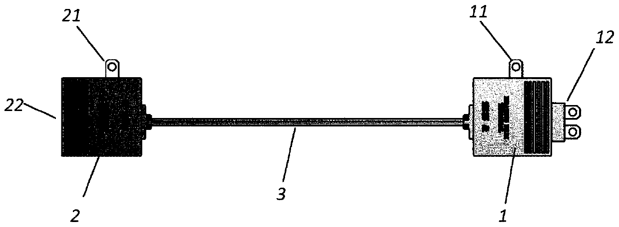
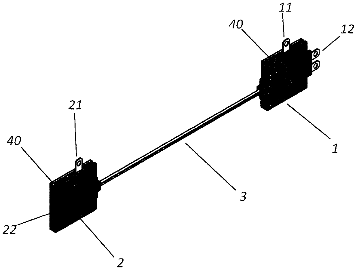
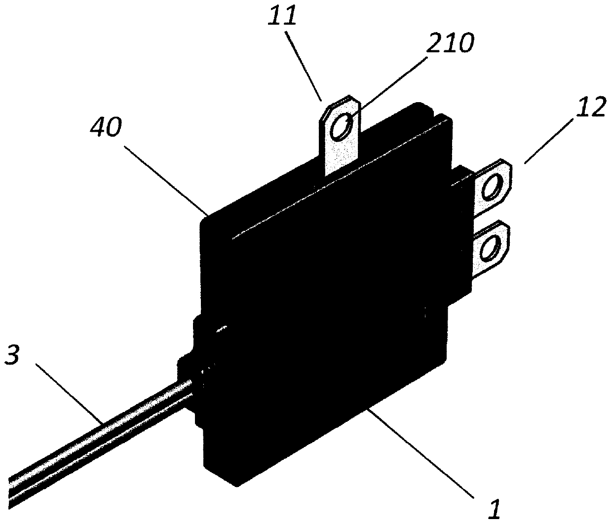
[0033] figure 1 It is a front view of the present invention, figure 2 It is an oblique view of the present invention, image 3 It is an enlarged oblique view of the male joint of the present invention, Figure 4 It is an oblique view of the connection between the male joint and the electrotherm...


PUM


Abstract

The present invention relates to a power connector dedicated to a heating film, comprising: a male connector formed in a quadrangular thin plate shape, the male connector having a power inlet plug formed on the right side thereof and having a first electrode for heating film wiring formed on the upper side thereof, a power cable internally wired to the power inlet plug being connected to the leftside of the male connector; and a female connector formed in a quadrangular thin plate shape, the power cable being connected to the right side of the female connector, the female connector having a second electrode for heating film wiring formed on the upper side thereof and having a power outlet socket formed on the left side thereof, the power outlet socket being internally wired to the power cable and wired to the power inlet plug. The power connector according to the present invention is characterized in that the power cable is wired, in a flat shape, to a copper foil electrode of a heating film that is installed on a plane after the length of the power cable is adjusted according to the distance of the copper foil electrode of the heating film, and power connection of a plurality ofarranged heating films is implemented by consecutive connections of the male connector and the female connector. The present invention advantageously provides a power connector dedicated to a heatingfilm configured such that power connection and grounding of a heating film and a grounded heating film, which is grounded, can be implemented simply, thereby reducing installation efforts and costs.

Description

technical field [0001] The present invention relates to a special power connector for electrothermal film, which is characterized in that it comprises: a male connector formed in the shape of a quadrangular thin plate, a power input plug is formed on the right side, a first electrode for connecting the electrothermal film is formed on the upper side, and a left side The side is connected to the power cable connected internally with the above-mentioned power inlet plug; and, the female connector is formed in the shape of a quadrangular thin plate, the right side is connected to the above-mentioned power cable, and the second electrode for electric heating film connection is formed on the upper side, and the left side is The side is internally connected with the above-mentioned power cable to form a power outlet socket connected to the above-mentioned power inlet plug; wherein, the length of the above-mentioned power cable is adjusted according to the distance between the copper ...

Claims


Application Information

Patent Timeline
Patent Type & Authority Applications(China)
IPC IPC(8): H01R4/18H01R13/10H05B3/08H05B3/20
CPCH05B3/08H05B3/36H05B3/145H05B2203/016H05B2203/026H01R24/20H01R24/28H01R4/06Y02B30/00H01R4/18H01R13/10H05B3/20H01R12/57H01R13/04H01R13/443
Inventor 金二泰
Owner SH KOREA CO LTD
Why Eureka
Try Eureka