Scanner having a light beam incident position adjusting device

a technology of incident position and scanning device, which is applied in the direction of discharge tube/lamp details, instruments, optical elements, etc., can solve the problems of difficult to finely adjust the incident position of the laser beam on the photo-detector, the position at which the photo-detector is to be arranged is quite limited, and the respective positions of the reflective mirror and the photo-detector cannot be easily adjusted from outside the laser-beam apparatus. to achieve the effect of finely

Inactive Publication Date: 2007-01-02
ASAHI KOGAKU KOGYO KK
View PDF15 Cites 28 Cited by
  • Summary
  • Abstract
  • Description
  • Claims
  • Application Information

AI Technical Summary

Benefits of technology

[0007]An object of the present invention is to provide a scanner provided with a device for adjusting the incident position of a light beam on a photo-detector used for determining the timing of commencement of writing each scanning line with respect to a scanning surface, wherein the adjusting device makes it possible to finely and easily adjust the incident position of the light beam on the photo-detector.
[0008]Another object of the present invention is to provide a scanner having such an adjusting device which makes it possible to finely and easily adjust the incident position even from outside the scanner.
[0026]According to another aspect of the present invention, there is provided a scanner including a light-beam emitter for emitting a light beam; a light-beam deflector for deflecting the light beam to scan a scanning surface; a photo-detector provided at a position outside an image-forming scanning range of the scanning surface to detect a scanning light beam before the scanning light beam starts generating a scanning line, the photo-detector generating an output signal upon detecting the scanning light beam to determine a timing of commencement of writing the scanning line with respect to the scanning surface; and an optical member for deflecting the scanning light beam to be incident on the photo-detector in a direction to vary the timing of the scanning light beam incident upon the photo-detector.

Problems solved by technology

In the former type of adjusting device, although the incident position of the laser beam on the photo-detector can be adjusted by rotating the reflecting mirror, it is difficult to finely adjust the incident position of the laser beam on the photo-detector.
In the latter type of adjusting device, the position at which the photo-detector is to be arranged is quite limited.
Moreover, in each type of adjusting device, in the case where the base on which the reflective mirror and the photo-detector are mounted is slightly deformed after a long period of use, the respective positions of the reflective mirror and the photo-detector deviate from their original positions.
In this case, the respective positions of the reflective mirror and the photo-detector cannot be easily adjusted from outside the laser-beam apparatus.

Method used


Image

  • Scanner having a light beam incident position adjusting device
  • Scanner having a light beam incident position adjusting device
  • Scanner having a light beam incident position adjusting device

Examples


Embodiment Construction

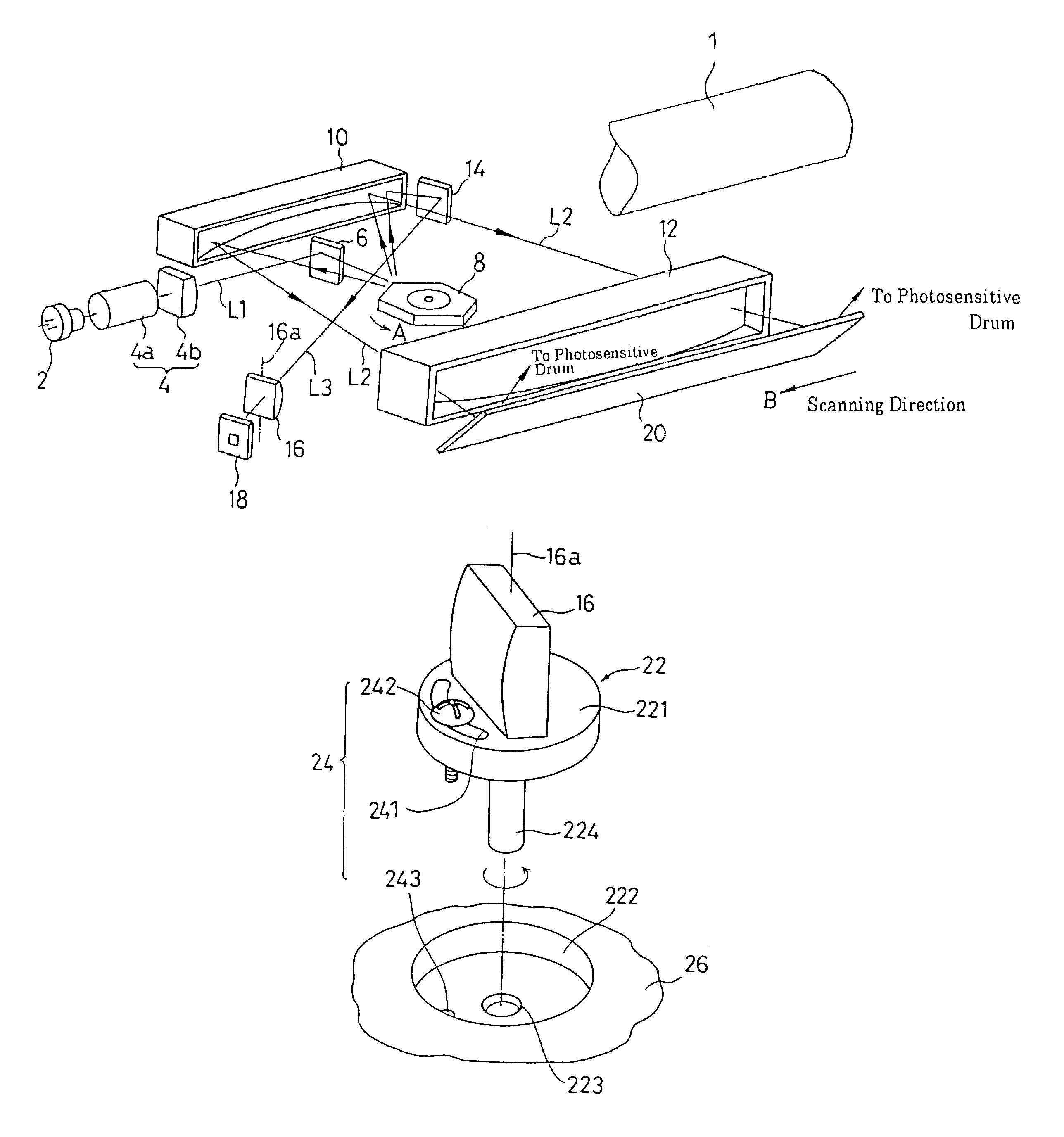
[0040]FIG. 1 shows the scanning optical system of a laser-beam scanner to which the present invention is applied. The laser-beam scanner scans the photoconductive surface of a photoconductive drum 1 (scanning surface). The laser beam scanner and the photoconductive drum 1 are positioned within a laser-beam printer as essential elements.

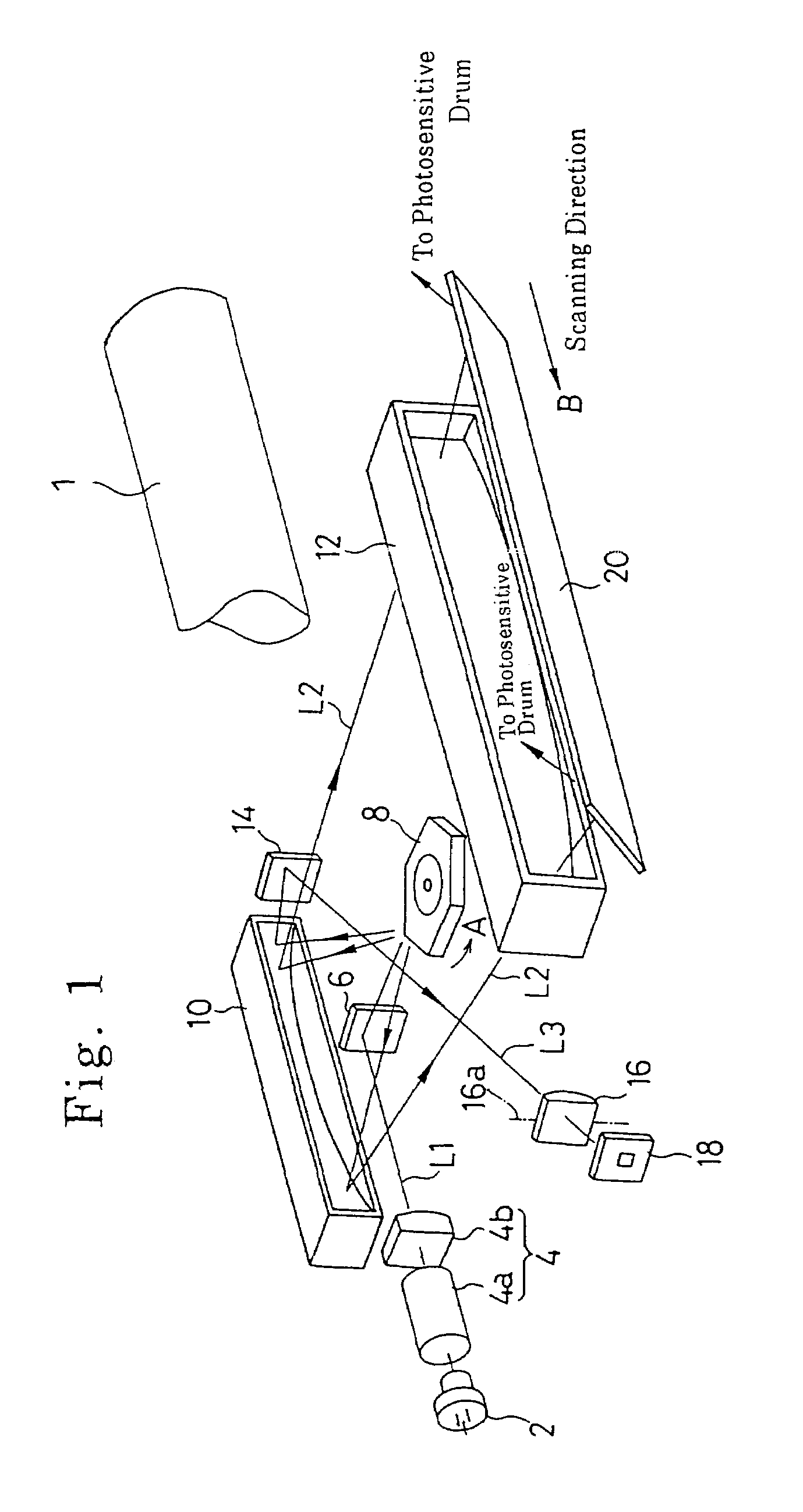
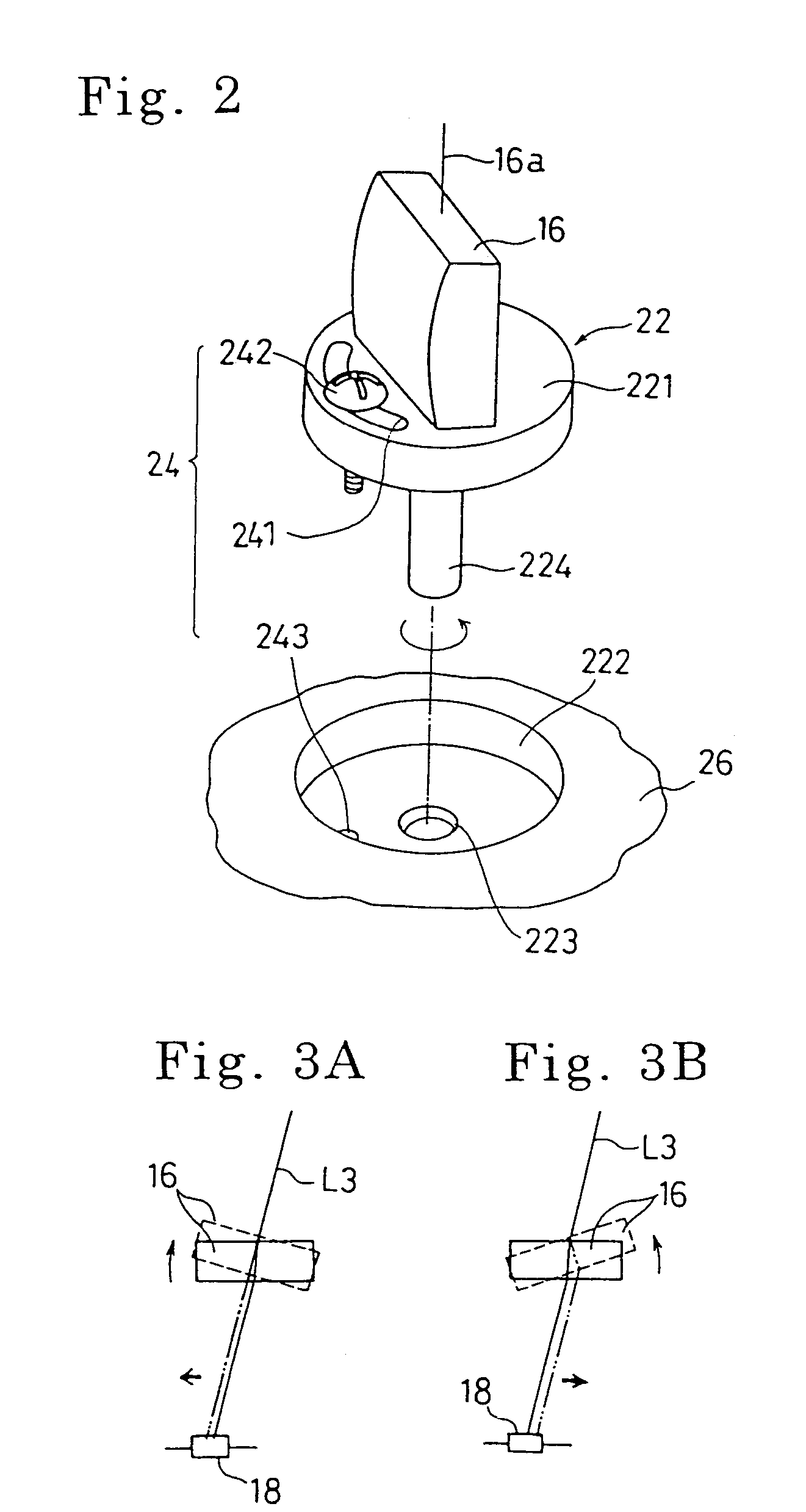
[0041]The scanning optical system of the laser-beam scanner is provided with a laser diode (light-beam emitter) 2, a collimating lens 4a, a cylindrical lens 4b, a reflecting mirror 6, a polygon mirror (light-beam deflector) 8, an fθ reflecting lens 10, an fθ lens 12, a reflecting mirror 14, a cylindrical lens (optical member) 16, and a laser-beam detector (photo-detector) 18. The collimating lens 4a and the cylindrical lens 4b together constitute an optical system 4 for the laser diode 2.

[0042]The laser diode 2 outputs a laser beam L1 modulated in accordance with image signals. The laser beam emitted from the laser diode 2 is collimated through the co...


PUM


Abstract

A scanner is provided that has a light-beam emitter for emitting a light beam, a light-beam deflector for deflecting the light beam to scan a scanning surface, a photo-detector provided at a position outside an image-forming scanning range of the scanning surface to detect a scanning light beam before the scanning light beam starts generating a scanning line in the image-forming scanning range, a rotatable member located in front of an incident surface of the photo-detector and positioned in a recess formed on an outer surface of a housing. The rotatable member is rotatable about a rotational axis perpendicular to a plane defined by the scanning light beam by said deflector. The scanner also has an optical member provided on the rotatable member that allows the scanning light beam to pass therethrough to be incident upon the incident surface of the photo-detector, and a device for adjusting rotational position of said rotatable member about said rotational axis. A through hole through which the optical member is inserted in the housing is formed at the bottom of the recess, and the optical member is inserted into the housing through the through hole.

Description

CROSS-REFERENCE TO RELATED APPLICATION[0001]This application is a divisional of U.S. patent application Ser. No. 10 / 098,544, filed Mar. 18, 2002 now U.S. Pat. No. 6,768,568, which is a divisional of U.S. patent application Ser. No. 09 / 271,455, filed Mar. 18, 1999, now abandoned, the disclosures of which are expressly incorporated herein by reference in their entireties.FIELD OF THE INVENTION [0002]The present invention relates to a scanner in which a light beam is deflected to scan a scanning surface, and more specifically to a scanner which is provided with a device for adjusting an incident position of a light beam on a photo-detector used for determining the timing of commencement of writing each scanning line with respect to a scanning surface.DESCRIPTION OF THE RELATED ART [0003]A laser-beam printer provided with a laser-beam scanner is well known. In a laser-beam printer, a laser beam which is modulated in accordance with image signals to be output from a laser-beam emitter is...

Claims


Application Information

Patent Timeline
Patent Type & Authority Patents(United States)
IPC IPC(8): H04N1/04H04N1/46G02B26/08H01J3/14G02B26/12
CPCG02B26/127G02B26/122
Inventor MORITA, TAKASHI
Owner ASAHI KOGAKU KOGYO KK
Why Eureka
Try Eureka