

Driving bit linking device in a box wrench
a technology of driving bit and box wrench, which is applied in the direction of wrenches, screwdrivers, manufacturing tools, etc., can solve the problems of deformation, only fitting the wrench b>10/b>, and not secure the e type bi
- Summary
- Abstract
- Description
- Claims
- Application Information
AI Technical Summary
Benefits of technology
Problems solved by technology
Method used
Image

Examples
Embodiment Construction
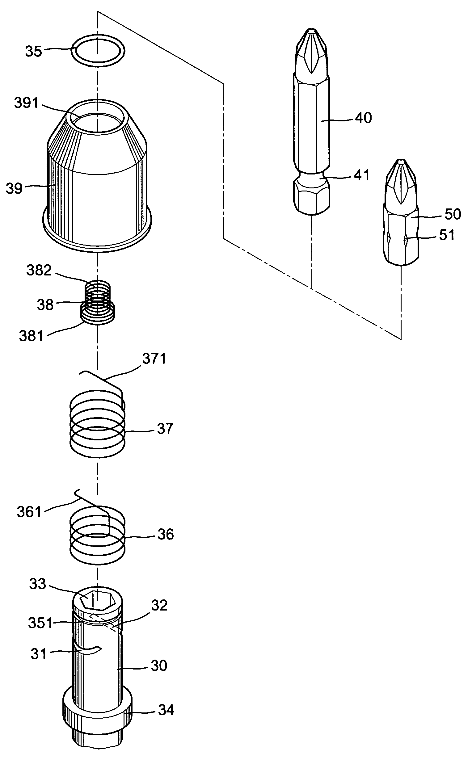
[0027]With reference to FIGS. 7, 8 and 9 of the drawings, the driving bit liking device of the present invention comprises a box wrench 30 having a hexagonal central bore 33 which may be circular, a bottom spring 38 embedded into the central bore 33 against the bottom of the wrench 30 including a large diameter loose lower portion 381 and a less diameter intensive upper portion 382, an annular collar 34 on a lower periphery, a pair of slant slots 31 and 32 form in the opposing middle peripheries at different level and an annular groove 251 in upper periphery abutting the upper rim for positioning a retaining ring 35, a pair of compression springs 36 and 37 sequentially wrapped on the outer periphery each having a transverse checking rod 361 and 371 on the top respectively engaged within the slant slots 31 and 32, a cap wrapped on the outer periphery of the box wrench 30 having a stop shoulder 391 on upper inner periphery retained by the retaining ring 35, a driving-bit 40 (ISO named...
PUM
 Abstract
Description
Claims
Application Information