Window sash latch

a window sash and latch technology, applied in the field of latches, can solve the problems of reducing the possibility of opening the latch from the underside of the sash, and allowing unwanted breakage into the premises

Active Publication Date: 2007-01-09
VISION INDS GROUP
View PDF20 Cites 58 Cited by
  • Summary
  • Abstract
  • Description
  • Claims
  • Application Information

AI Technical Summary

Problems solved by technology

Such access provides the opportunity for unwanted breaking into the premises behind the sliding windows.
The mechanism of the latch is designed in such way that reduces the possibility of opening the latch from the under side of the sashes.

Method used


Image

  • Window sash latch
  • Window sash latch
  • Window sash latch

Examples


Embodiment Construction

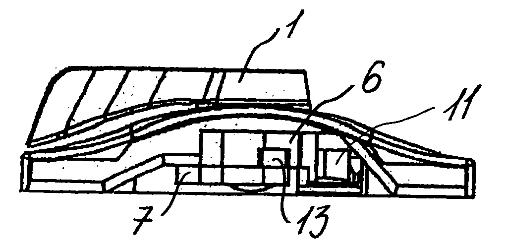
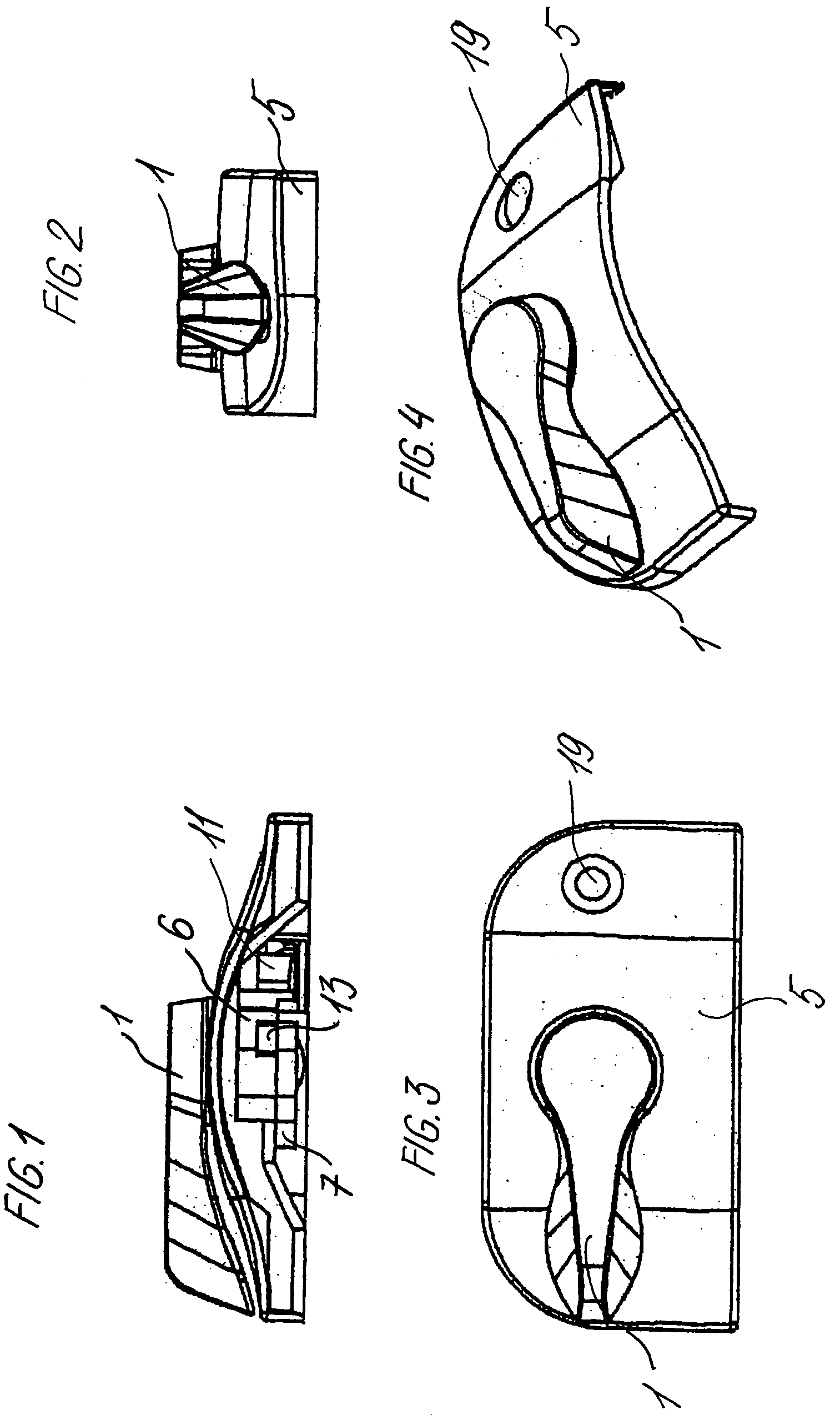
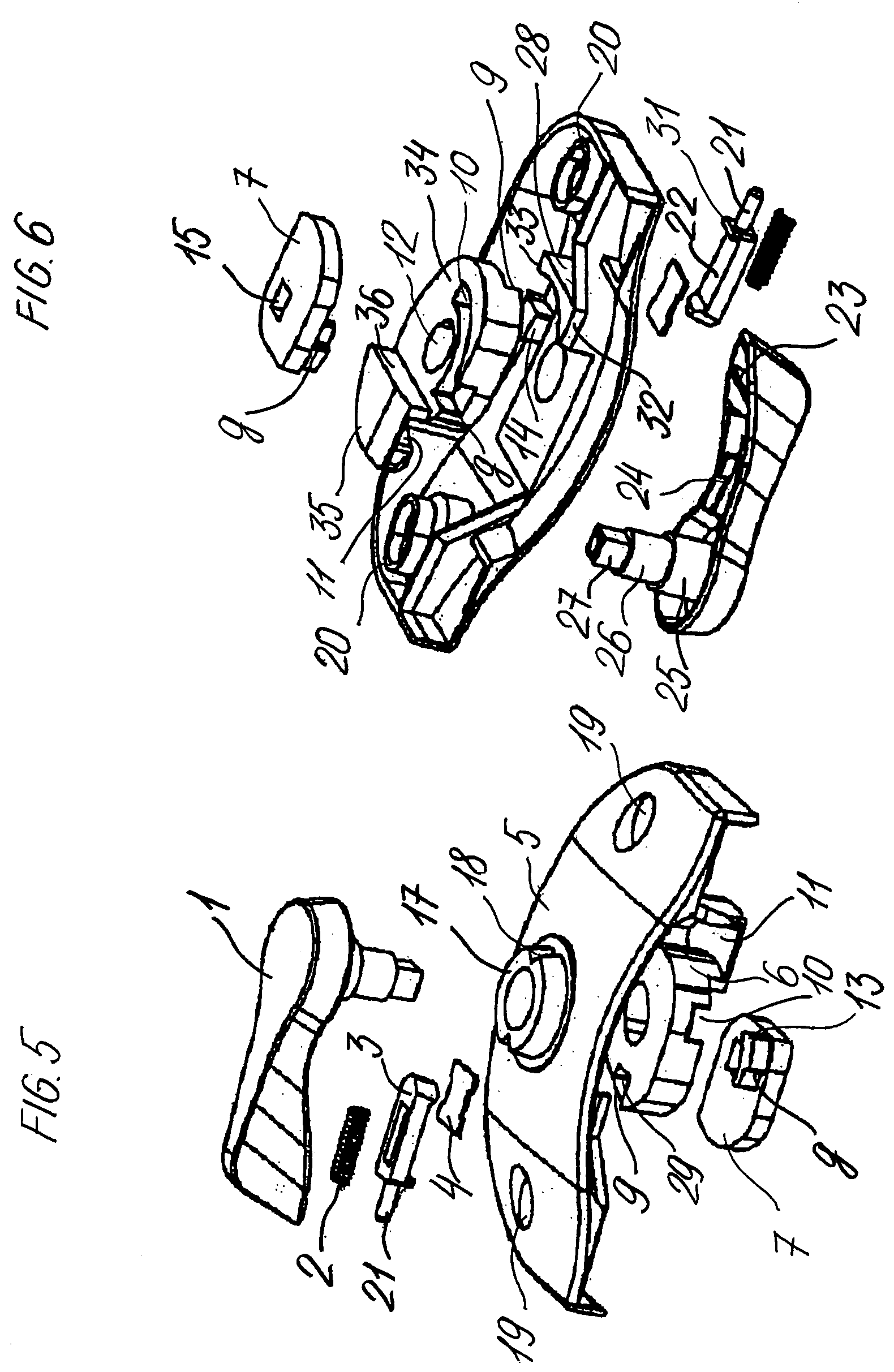
[0034]In one embodiment of the present invention there is generally a handle 1, a spring2, a bar 3, a plate 4, a housing 5, a first cam 6, a delay cam 7 and a keeper 8.

[0035]The housing 5 may generally be any suitable shape. In one embodiment the housing may be rectangular in shape with preferably two square corners on the side of the sash lock that is closest to the keeper 8, and on the opposite side of the housing there may be two rounded or squared corners depending of the “look” or style of the sash lock. Viewing the sash lock from the side having the squared corners, the housing has an open cavity which for example, may resemble an arch or raised portion. Residing in the cavity are the first cam 6 and the delay cam 7 which are preferably covered by the housing. Housing 5 may be provided with two screw holes 19 to mount the latch to the window sash. Underneath these holes the housing may have two pillars 20 that have such length that when latch is placed on a flat surface, the b...


PUM


Abstract

An improved window sash latch which has a locking mechanism and a keeper is provided with a handle that rotates from a “locked” to an “unlocked” position. An inner cavity of the handle has a spring assembly having a sliding part that can be forced into a detent as the handle slides around a cylindrical extension of an outer surface of the latch. The detents correspond to a “locked” and an “unlocked” position of the latch. The latch also provides two cams where both cams revolve relative to each other; one cam is activated by the handle through the handle's shaft, the other cam engages the keeper, and both cams engage each other.

Description

FIELD OF THE INVENTION[0001]The present invention is directed to latches for sliding windows such as double hung windows as well as other types of windows that may pivot around the axis for opening. More specifically, the present invention provides for convenient, resistant to the forced entry, and aesthetically appealing latch that may be maintained on the sash of the sliding windows.BACKGROUND OF THE INVENTION[0002]Sliding windows such as double hung have won worldwide application for many types of residential and commercial structures, various types of vehicles, boats, flying apparatus, etc. Sliding windows have acquired such a universal popularity in part because they are convenient and save space, they provide easy and suitable access and have many other advantages.[0003]Usually the sliding windows consist of a pair of window sashes, preferably equal in size, each of which moves independently along the parallel tracks that are contained within the inner sides of a single frame ...

Claims


Application Information

Patent Timeline
Patent Type & Authority Patents(United States)
IPC IPC(8): E05C3/14
CPCE05B73/007Y10S292/35Y10S292/07Y10S292/47Y10S292/20E05B15/0053E05B15/102E05B17/208E05B17/2084E05B65/0841E05C3/045E05C3/046E05C2007/007Y10T70/5146Y10T70/515Y10T292/0853Y10T292/0854Y10T292/0857Y10T292/0969Y10T292/1039Y10T292/104Y10T292/1041Y10T292/1077
Inventor LIANG, LUKE
Owner VISION INDS GROUP
Why Eureka
Try Eureka