
Sash lock with forced entry resistance

a technology of forced entry and lock, which is applied in the direction of mechanical controls, carpet fasteners, keyhole guards, etc., can solve the problem of leg not being prevented

Inactive Publication Date: 2012-06-26
ASHLAND HARDWARE LLC
View PDF214 Cites 36 Cited by
  • Summary
  • Abstract
  • Description
  • Claims
  • Application Information

AI Technical Summary

Benefits of technology

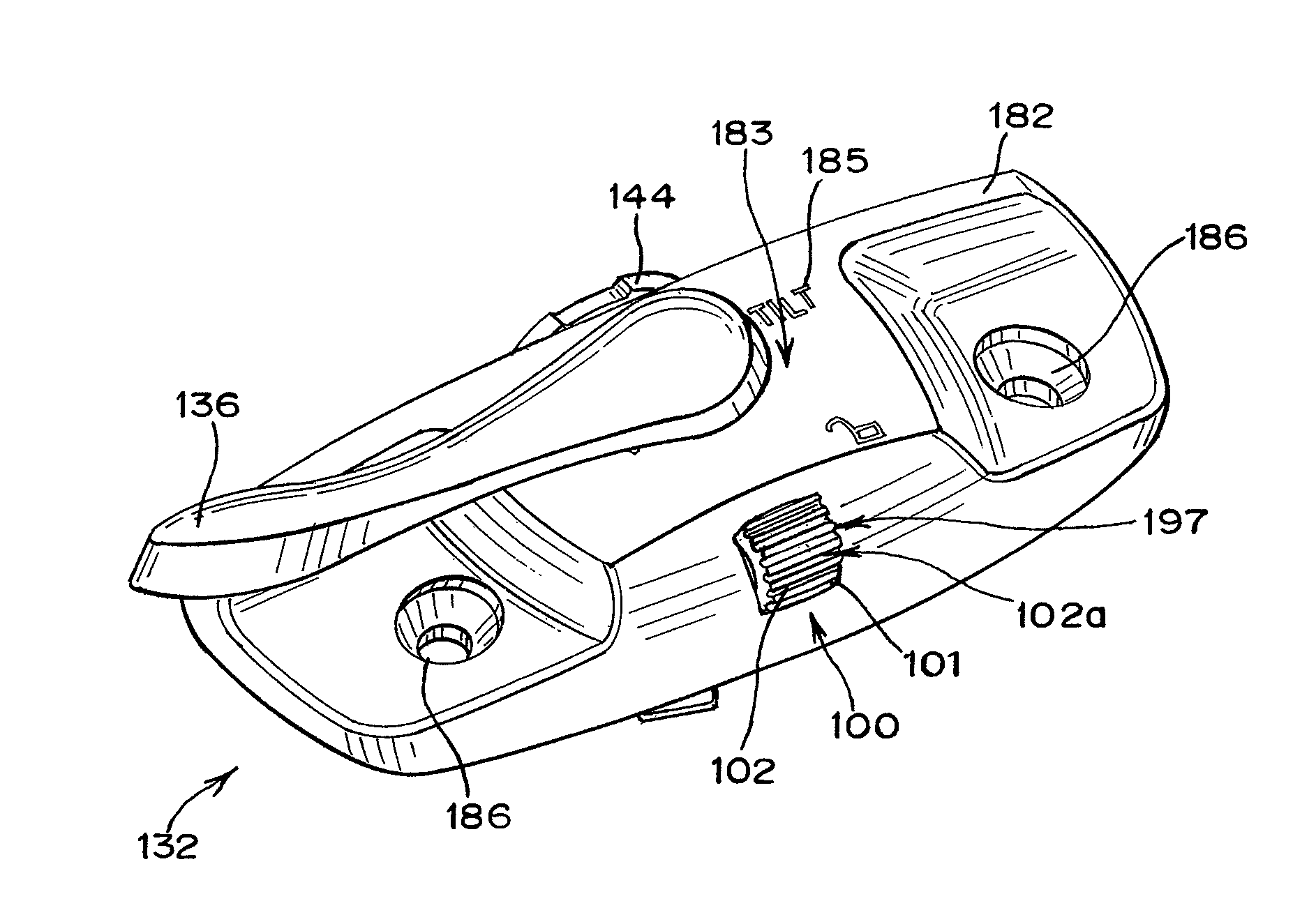
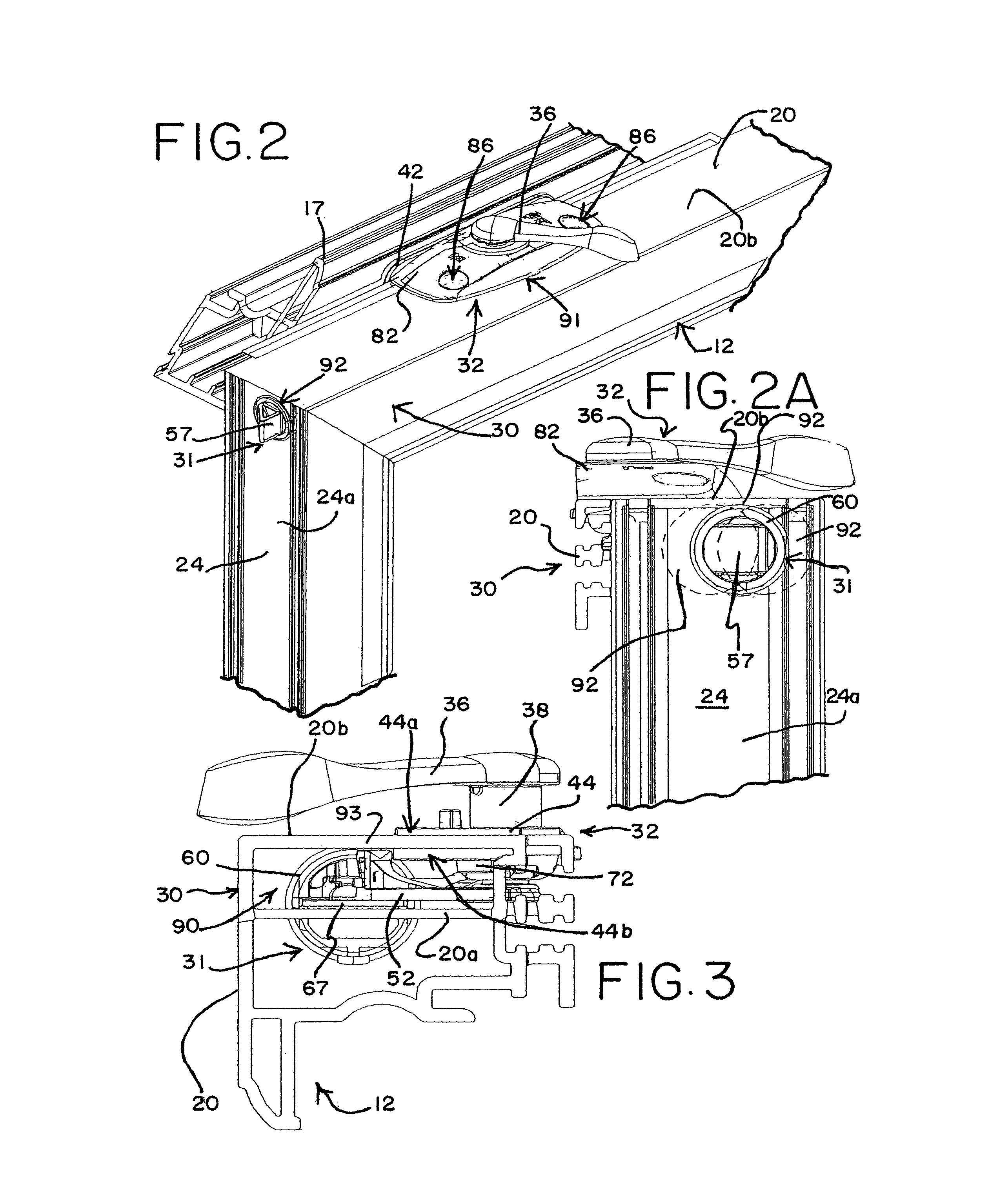
"The present invention relates to a sash lock mechanism for a window assembly. The mechanism includes a handle, a housing, and a rotor. The rotor is moveable between locked and unlocked positions by movement of the handle. The mechanism also includes a locking mechanism with a pivotable member that can be pivoted between a first and second position. When the rotor is in the locked position and the pivotable member is in the first position, the pivotable member engages the rotor to prevent it from moving. When the pivotable member is in the second position, the pivotable member does not prevent the rotor from moving. The pivotable member includes an actuator with a leg and an engagement surface that prevents the rotor from moving when the pivotable member is in the first position. The mechanism also includes means for rotationally biasing the pivotable member to the first position, such as a leaf spring. The pivotable member has a tactile outer surface accessible through an opening in the housing. The technical effects of the invention include improved security and ease of use for window assemblies."

Problems solved by technology

When the pivotable member is in the second position, the pivotable member does not prevent movement of the rotor.
When the pivotable member is in the second position and the leg is elevated above the rotor, the leg does not prevent the rotor from moving to the unlocked position.

Method used


Image

  • Sash lock with forced entry resistance
  • Sash lock with forced entry resistance
  • Sash lock with forced entry resistance

Examples


Embodiment Construction

[0091]While this invention is susceptible of embodiment in many different forms, there is shown in the drawings, and will herein be described in detail, preferred embodiments of the invention with the understanding that the present disclosure is to be considered as an exemplification of the principles of the invention and is not intended to limit the broad aspect of the invention to the embodiments illustrated.

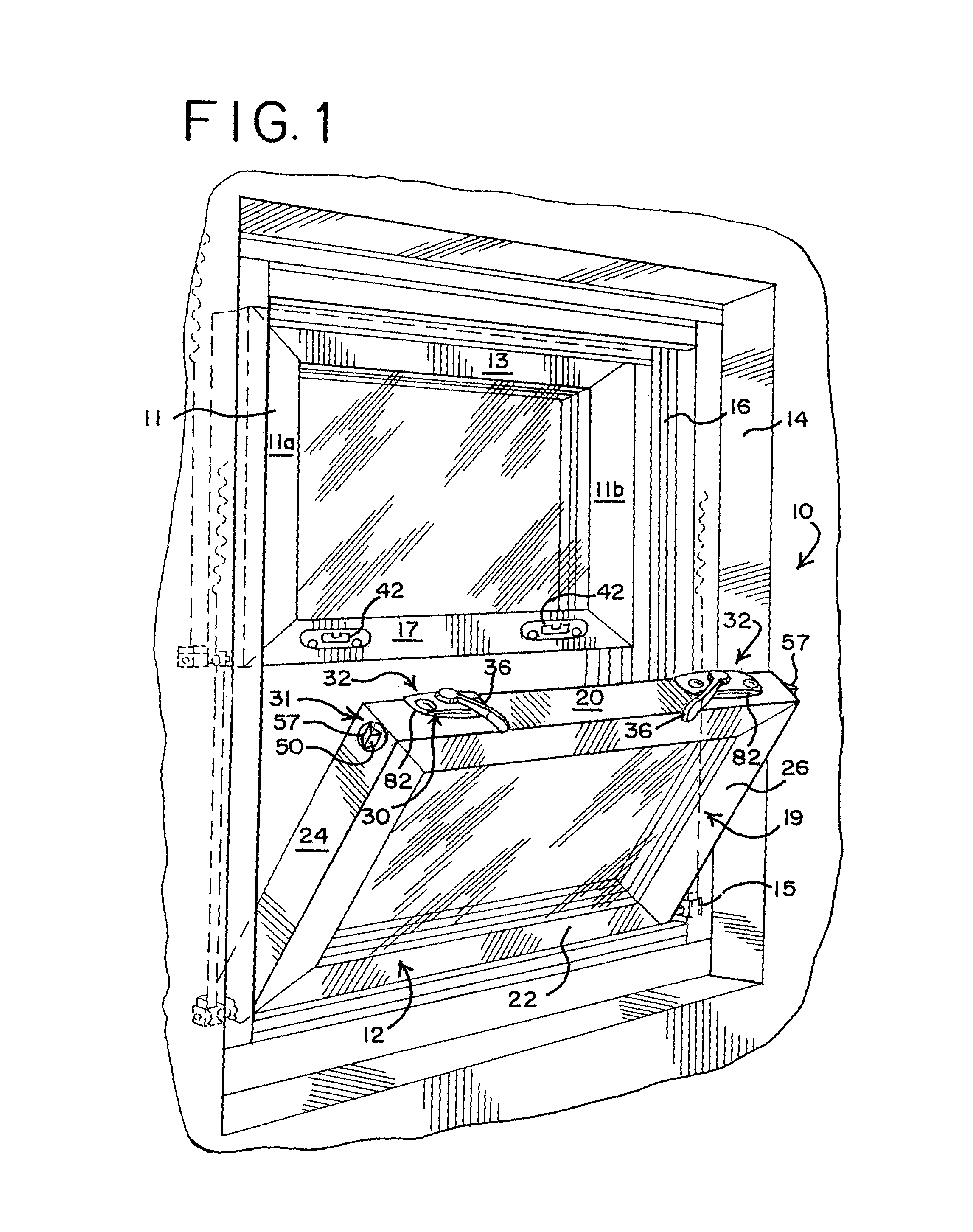
[0092]A sash window assembly 10 is shown in FIG. 1. The sash window assembly 10 is a double-hung window assembly having a pivotal bottom sash window 12 installed in a master frame 14. The bottom sash window 12 is pivotally mounted to the master frame 14 by a pivot-corner / balance shoe assembly 15. The master frame 14 has opposed, vertically extending guide rails 16 or jambs 16. The bottom sash window 12 has a top sash rail 20, a base 22 or bottom sash rail 22 and a pair of stiles 24,26 or side rails 24,26, cooperatively connected together at adjacent extremities thereof to form...


PUM


Abstract

A sash lock mechanism includes a handle, a housing adapted to be supported by a sash window assembly, the housing having an opening receiving the handle therethrough, and a rotor coupled to the handle. The rotor is moveable between at least a locked position and an unlocked position by movement of the handle. The sash lock mechanism also includes a locking mechanism that contains a pivotable member pivotably connected to the housing. The pivotable member is pivotable between a first position and a second position. When the rotor is in the locked position and the pivotable member is in the first position, the pivotable member confronts the rotor to prevent movement of the rotor to the unlocked position. When the pivotable member is in the second position, the pivotable member does not prevent movement of the rotor.

Description

TECHNICAL FIELD[0001]The present invention relates to sash window hardware and, more particularly, to an integrated sash lock and tilt-latch for use in sash windows wherein the sash lock has forced entry resistance capabilities.BACKGROUND OF THE INVENTION[0002]A pivotal sash window adapted for installation in a master frame of a sash window assembly is well-known. The pivotal sash window assembly typically has opposed, vertically extending jambs or guide rails to enable vertical reciprocal sliding movement of the sash window in the master frame while cooperatively engaged with the guide rails. The sash window also has a top sash rail, a base or lower rail and a pair of stiles or side rails cooperatively connected together at adjacent extremities thereof to form a sash frame, usually a rectangular frame.[0003]Hardware is associated with the sash window assembly, such as a sash lock that provides a locking mechanism between an upper sash window and a lower sash window, as well as tilt...

Claims


Application Information

Patent Timeline
Patent Type & Authority Patents(United States)
IPC IPC(8): E05C3/04E05C3/00
CPCE05B13/004E05B53/00E05C1/12E05C3/046E05B65/06E05B65/0841E05B2063/0082Y10S292/20Y10S292/47Y10T70/20Y10T70/5146Y10T70/515Y10T292/1041
Inventor FLORY, EDWARD C.
Owner ASHLAND HARDWARE LLC
Learn More