Hinge for a roof window with a pivot sash

a technology of hinges and roof windows, which is applied in the direction of hinges, manufacturing tools, wing accessories, etc., can solve the problems of deteriorating aesthetics and inability of windows to be fixed

Inactive Publication Date: 2012-02-07
FAKRO PP SPOLKA Z O O
View PDF11 Cites 36 Cited by
  • Summary
  • Abstract
  • Description
  • Claims
  • Application Information

AI Technical Summary

Problems solved by technology

A bigger shift of the sash rotation axis or any additional equipment on any of its parts, the lower or the upper, disturbs the balance and causes that a window is unable to hold its sash in each ajar position and a user operating the window has to use more strength to overcome the unbalanced weight of the sash.
The auxiliary device constitutes an additional fixture of a roof window and it requires performing of additional activities during assembly of a window and during installation of a window in a roof, it deteriorates aesthetics of the window in an ajar position of the sash, moreover if the need arises to remove a sash from a window frame the cylinder must be disconnected from the window frame beforehand.

Method used


Image

  • Hinge for a roof window with a pivot sash
  • Hinge for a roof window with a pivot sash
  • Hinge for a roof window with a pivot sash

Examples


example i

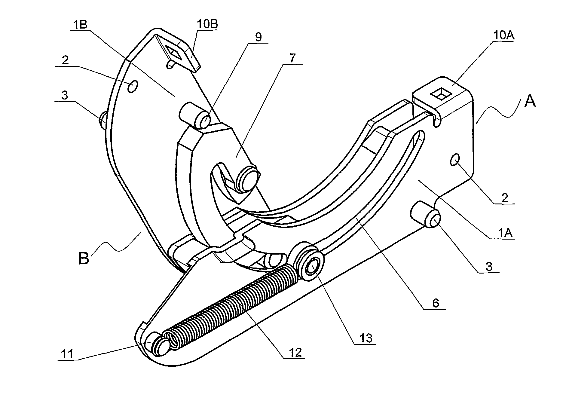
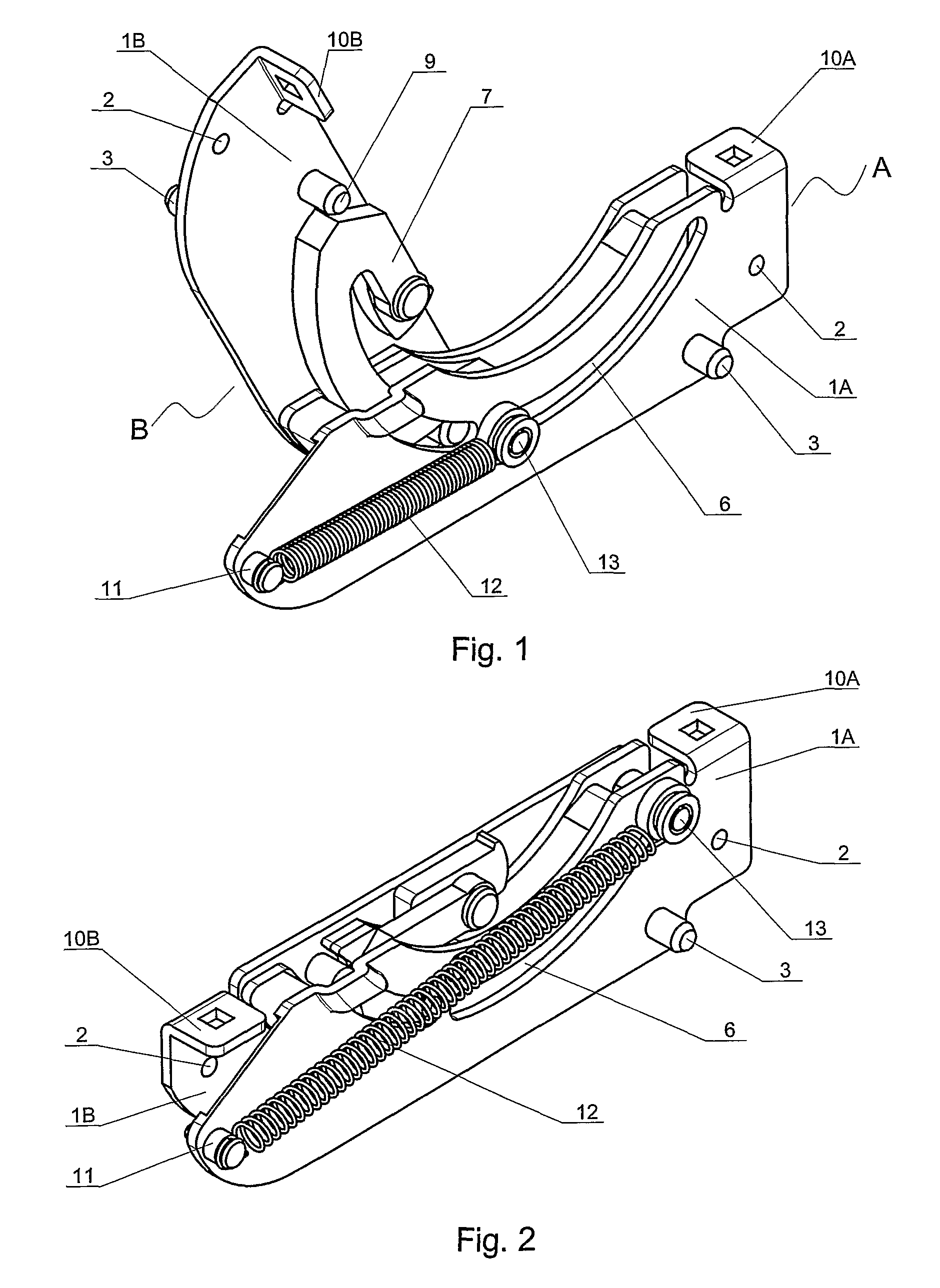
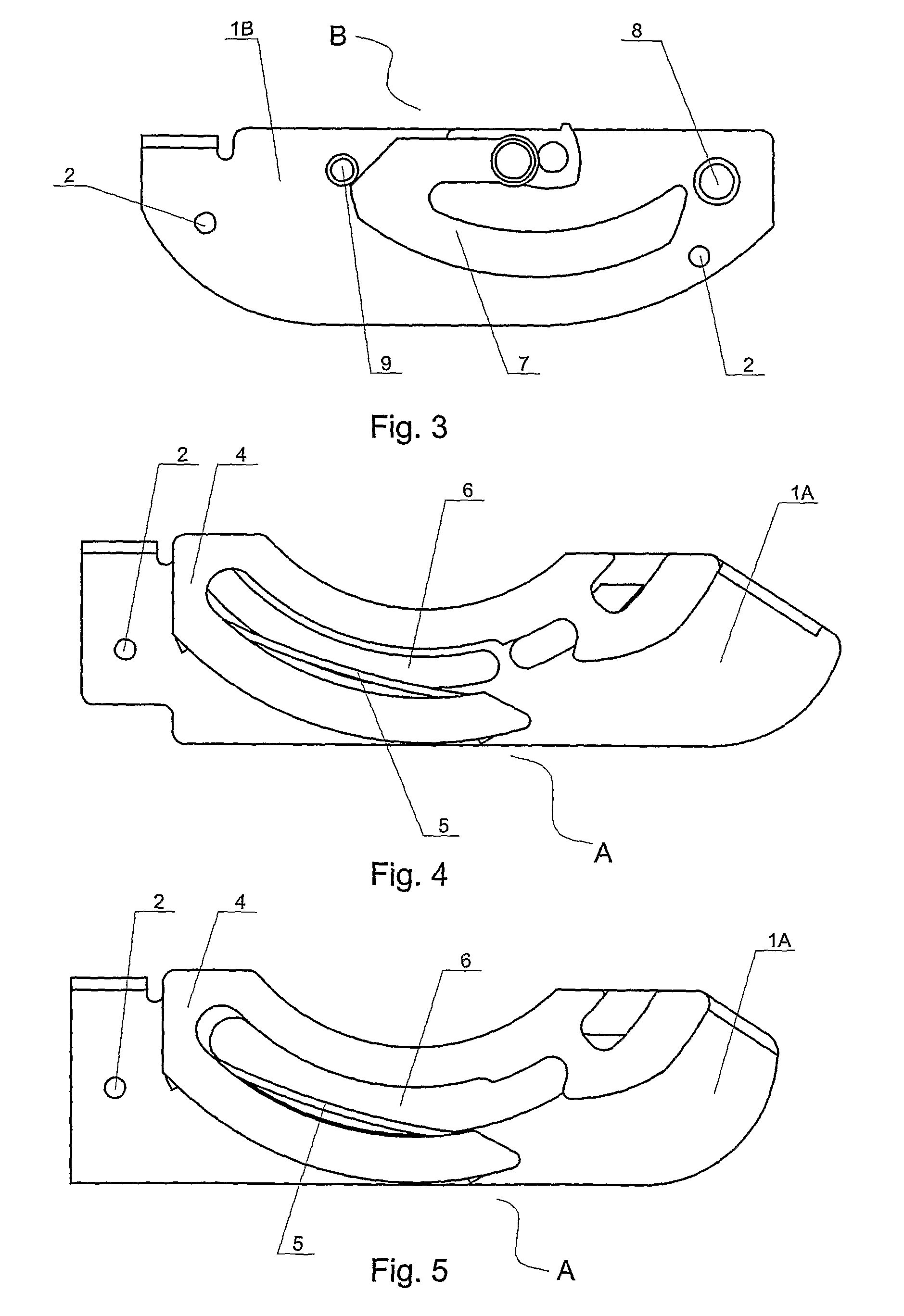
[0009]A hinge for a roof window with a pivot sash comprises a hinge part A, secured to the side member of a window frame and a hinge part B secured to the side member of a sash frame. Both hinge parts have base plates 1A and 1B with screw holes 2 for fastening screws with additional fastening members 3 on one surface. At the other surface the base plate 1A has an arch-bent guide 4 inside of which a friction spring 5 is secured and a through elongated hole 6 is made in the plate 1A between arched members of the guide 4. The base plate 1B has a pivoting hook 7 with an arch-bent arm, a guide pin 8 and a bumper 9 limiting the range of the hook 7 pivoting. The arch bent arm of the hook 7 and the guide pin 8 mate the guide 4 and the friction spring 5.

[0010]The base plates 1A and 1B at one end have fasteners 10A and 10B for securing external cover members, at the same time after securing the plate 1A to the side member of a window frame, the fastener 10A is located above the sash rotation ...

example ii

[0015]A hinge for a roof window with a pivot sash comprises a hinge part A, secured to the side member of a window frame and a hinge part B secured to the side member of a sash frame. Both hinge parts have base plates 1A and 1B with screw holes 2 for fastening screws with additional fastening members 3 on one surface. At the other surface the base plate 1A has an arch-bent guide 4 inside of which a friction spring 5 is secured and a through, elongated recess 6 is made in the plate 1A between arched members of the guide 4. The base plate 1B has a pivoting hook 7 with an arch-bent arm, a guide pin 8, which protrudes beyond the base plate 1A through the recess 6, and a bumper 9 limiting the range of hook 7 pivoting. The arched arm of the hook 7 and the guide pin 8 mate the guide 4 and the friction spring 5.

[0016]The base plates 1A and 1B at one end have fasteners 10A and 10B for securing external cover members, at the same time after securing the plate 1A to the side member of a window...

example iii

[0021]A hinge for a roof window with a pivot sash comprises a hinge part A, secured to the side member of a window frame and a hinge part B secured to the side member of a sash frame. Both hinge parts have base plates 1A and 1B with screw holes 2 for fastening screws with additional fastening members 3 on one surface. At the other surface the base plate 1A has an arch-bent guide 4 inside of which a friction spring 5 is mounted and a through, elongated recess 6 is made in the plate 1A between arched members of the guide 4. The base plate 1B has a pivoting hook 7 with an arch-bent arm, a guide pin 8, which protrudes beyond the base plate 1A through the recess 6, and a bumper 9 limiting the range of hook 7 pivoting. The arched arm of the hook 7 and the guide pin 8 mate the guide 4 and the friction spring 5.

[0022]The base plates 1A and 1B at one end have fasteners 10A and 10B for securing external cover members, at the same time after securing the plate 1A to the side member of a window...


PUM


Abstract

A pivot hinge for roof windows with a sash pivoting around the axis located between the upper and the lower member of a window, has a balancing system, which ensures the state of equilibrium of a window sash when its centre of gravity is located outside the sash rotating axis and the friction spring of the hinge is unable to hold the sash pivoted in each its position. At the same time the window fittings, its assembly, installation in a roof and its appearance remain unchanged. Also the method of separating of both hinge parts (taking a sash out of a window frame) remains unchanged.

Description

BACKGROUND OF THE INVENTION[0001]The present invention concerns a hinge for a roof window with a sash pivoting around an axis located between the upper and the lower member of a window.[0002]A roof window with a pivot function is at both sides equipped with pivot hinges, comprising two hinge parts, one hinge part secured to the side member of a window frame, and the other hinge part secured to the side member of a sash. Each hinge part has a base plate for securement by fastening screws through screw holes.[0003]One side of each base plate has additional means for securing the plate to a window frame or a sash and the other side of the base plate has members mating one another, which connect both plates, enabling their separation, and enable pivoting of the base plates relative to each other. The members constitute: an arched, one-sided open guide with a friction spring located on the base plate secured to a window frame, and a pivoting hook with an arch-bent arm, a guide pin and a ...

Claims


Application Information

Patent Timeline
Patent Type & Authority Patents(United States)
IPC IPC(8): E05D11/06
CPCE05D1/04E05D7/086E05F1/1276E05Y2900/148Y10T16/6298Y10T16/304Y10T16/54038Y10T16/544E05Y2900/152E05D7/084E05F1/1261
Inventor FLOREK, RYSZARD
Owner FAKRO PP SPOLKA Z O O
Why Eureka
Try Eureka