System for detecting structural defects and features utilizing blackbody self-illumination

a self-illuminating and structural technology, applied in the field of structural features detection, can solve the problems of constant degradation of aircraft components, inability to eliminate them completely, and inability to mitigate the effect of coating of paint, so as to maximize the viewing clarity of defects and selectively view defects

Inactive Publication Date: 2007-01-16
NORTHROP GRUMMAN SYST CORP
View PDF38 Cites 15 Cited by
  • Summary
  • Abstract
  • Description
  • Claims
  • Application Information

AI Technical Summary

Benefits of technology

[0009]The present invention utilizes the substantially steady-state temperature of a coated object, in conjunction with an optical detection system, to selectively view defects and features of the object below the coating without the necessity of transient heating or IR illumination and reflectance imaging. The optical detector, such as an IR camera, may be tailored for the wavelengths at which the coating material is substantially transparent, thereby maximizing the viewing clarity of the defects and features under the coating, and distinguishing them from any spurious features on the top surface of the coating. The present system enables the inspection of small or large areas in real time, without requiring complex image acquisition, storage and image processing equipment and software.

Problems solved by technology

Aircraft components are subject to constant degradation such as corrosion and cracking caused by environmental and operational conditions.
Although the application of coatings, such as paints, reduces corrosion problems substantially, they typically cannot eliminate them entirely.
Furthermore, stress experienced during flight can result in damage which a coating of paint cannot mitigate, such as stress defects and cracking.
When visually inspecting aircraft components, the coating used to protect the components becomes an obstacle because it may hide structural defects or features beneath the coating.
This process results in substantial expense in the form of labor and materials, raises environmental concerns, and requires a great amount of time.
Apart from the inefficiency of visual inspection methods, another problem is that visual inspection is not always effective.
While a skillful eye may pick up most human-visible defects with a satisfactory degree of consistency, some defects may be very small or lie under the surface of the component.
In many cases these defects will go unnoticed by visual inspection regardless of the skill and experience of the observer.
However, such techniques require specialized equipment and controls to generate the necessary transient heating, and are inefficient because detection of the transient thermal signature can require a significant amount of time.
Furthermore, a portion of the incident radiation may reflect off the surface of the coating, thereby obscuring the image of the underlying substrate.

Method used


Image

  • System for detecting structural defects and features utilizing blackbody self-illumination
  • System for detecting structural defects and features utilizing blackbody self-illumination
  • System for detecting structural defects and features utilizing blackbody self-illumination

Examples


example 1

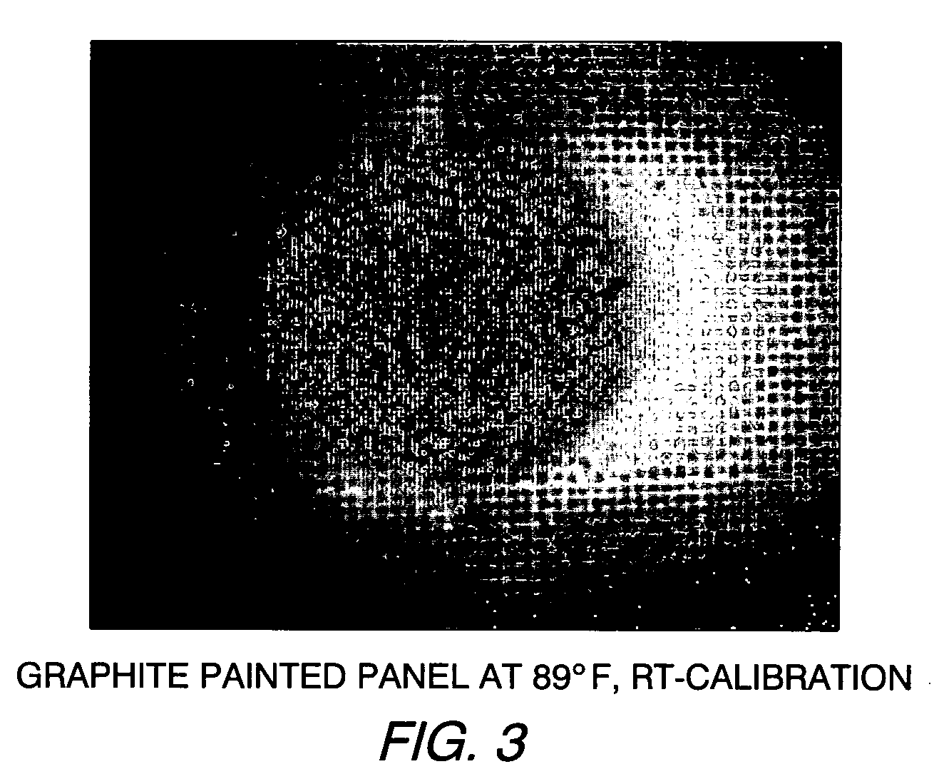
[0030]As shown in FIG. 3, a painted graphite panel comprising epoxy graphite with an epoxy primer and urethane top coat paint was imaged with a mid-IR camera at the wavelength of 3 to 5 microns. During the imaging process, the panel was held at 89° F. The panel was subjected to a room temperature calibration which involved adjusting pixel intensity to make focal plane uniform and linear within selected room temperature (RT) calibration.

example 2

[0031]As shown in FIG. 4, a painted graphite panel comprising epoxy graphite and epoxy primer and urethane top coat paint was imaged with a mid-IR camera at a wavelength of 3 to 5 microns with the panel held at a temperature of 90° F. The panel was subjected to hot calibration at a temperature of 84° F. The hot calibration process involved adjusting pixel intensity to make focal plane uniform and linear within selected 84° F. calibration.

example 3

[0032]As shown in FIG. 5, a composite panel comprising epoxy graphite and laminated copper fiber painted with epoxy primer and urethane top coat was imaged with a mid-IR camera at a wavelength of 3 to 5 microns, with the panel maintained at a temperature of 90° F. The panel was subjected to hot calibration at 84° F., as described above.


PUM

PropertyMeasurementUnit
temperatureaaaaaaaaaa

Abstract

A system is disclosed which utilizes the substantially steady-state temperature of a coated object, in conjunction with an optical detection system, to selectively view defects and features of the object below the coating without the necessity of transient heating or IR illumination and reflectance imaging. The optical detector, such as an IR camera, may be tailored for the wavelengths at which the coating material is substantially transparent, thereby maximizing the viewing clarity of the defects and features under the coating, and distinguishing them from any spurious features on the top surface of the coating. The present system enables the inspection of small or large areas in real time, without requiring complex image acquisition, storage and image processing equipment and software.

Description

GOVERNMENT CONTRACT[0001]The United States Government has certain rights to this invention pursuant to Contract No. DACA 72-99-C-011 awarded by SERDP.FIELD OF THE INVENTION[0002]The present invention relates to detection of structural features, and more particularly relates to a system which utilizes blackbody self-illumination to observe defects and other structural features of coated objects such as aircraft components.BACKGROUND INFORMATION[0003]Aircraft components are subject to constant degradation such as corrosion and cracking caused by environmental and operational conditions. Although the application of coatings, such as paints, reduces corrosion problems substantially, they typically cannot eliminate them entirely. Furthermore, stress experienced during flight can result in damage which a coating of paint cannot mitigate, such as stress defects and cracking. In order to ensure that aircraft are ready for flight, periodic inspections are necessary.[0004]Inspection of aircra...

Claims


Application Information

Patent Timeline
Patent Type & Authority Patents(United States)
IPC IPC(8): G01N21/86G01J5/00
CPCG01N21/88G01N25/72G01N21/8422G01J2005/0077G01N21/3563G01N2021/8472
Inventor WEIR, JOHN DOUGLASDIMARZIO, DONALDCHU, STEVENSILBERSTEIN, ROBERT P.
Owner NORTHROP GRUMMAN SYST CORP
Why Eureka
Try Eureka