Method and apparatus for machine element control

a machine element and control method technology, applied in the direction of electric programme control, instruments, ways, etc., can solve the problems of complicated arrangement, and achieve the effect of facilitating the reacquisition of targets

Active Publication Date: 2007-01-30
TRIMBLE NAVIGATION LTD
View PDF77 Cites 66 Cited by
  • Summary
  • Abstract
  • Description
  • Claims
  • Application Information

AI Technical Summary

Benefits of technology

[0018]The step of acquiring the targets in succession comprises the step of storing the detected locations of each of the targets and the movement history of each of the targets, and predicting the locations of each of the targets as the laser beam is directed repeatedly in succession to each of targets, whereby the reacquisition of the targets is facilitated.

Problems solved by technology

Such arrangements have been somewhat complicated.

Method used


Image

  • Method and apparatus for machine element control
  • Method and apparatus for machine element control
  • Method and apparatus for machine element control

Examples


Embodiment Construction

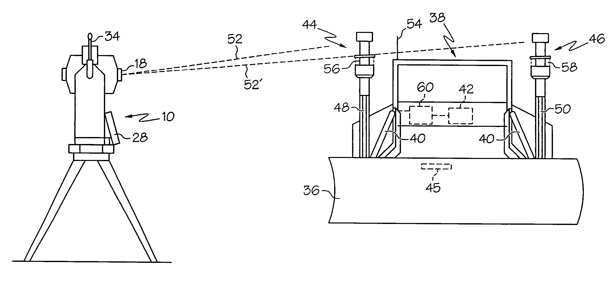
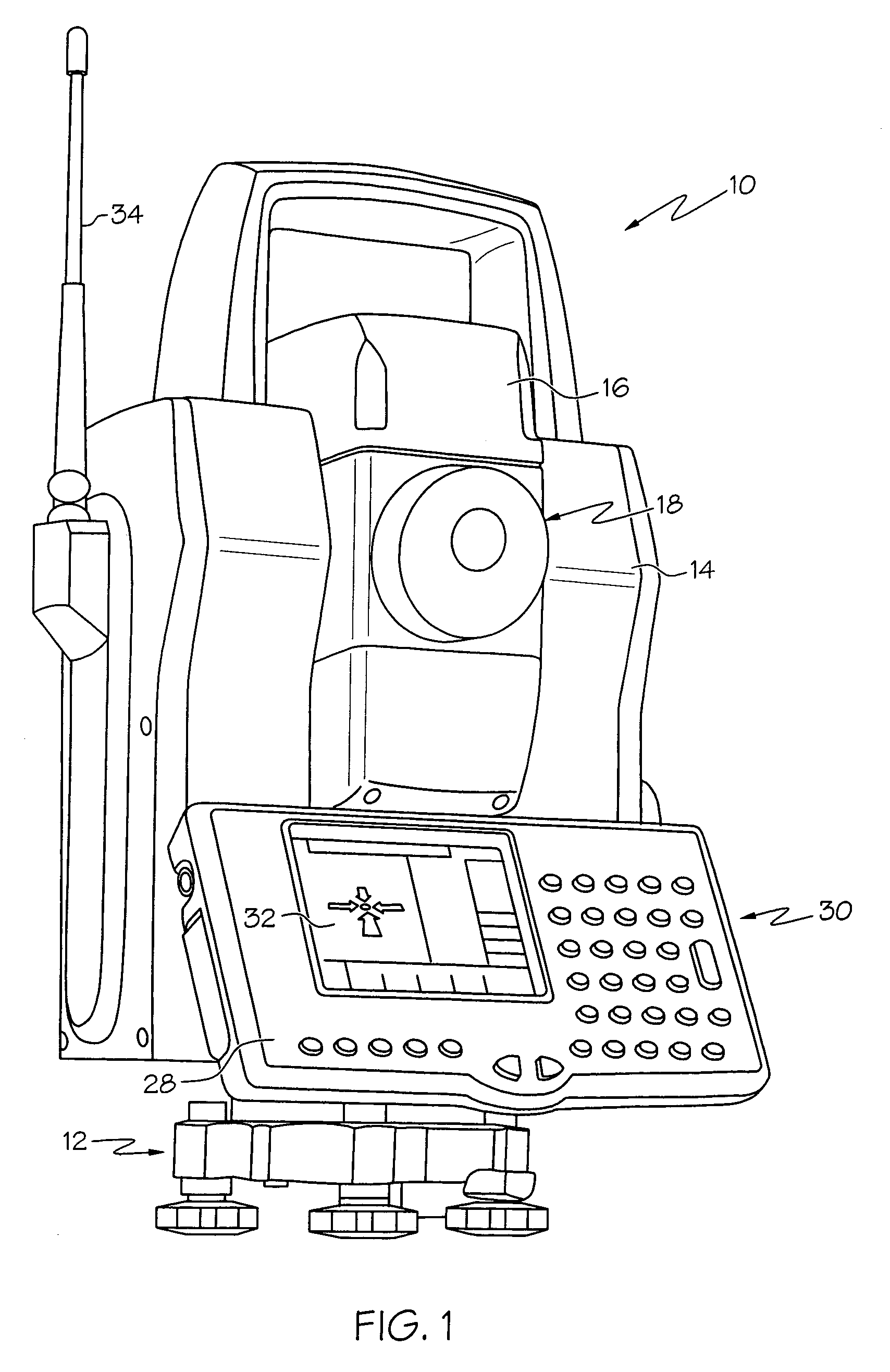
[0027]Reference is made to FIGS. 1–3, which illustrate the apparatus and method of the present invention for monitoring the location and orientation of a machine element, and controlling the movement of the machine element. FIG. 1 depicts a robotic total station 10, which is comprised of a base portion 12, a rotational alidade portion 14, and an electronic distance-measuring portion 16. Rotational alidade portion 14 rotates on base portion 12 about a vertical axis, with a full 360-degree range of rotation. Electronic distance-measuring portion 16 similarly rotates within rotational alidade portion 14 about a horizontal axis. With this arrangement, it is possible for the distance-measuring portion 16 to be oriented toward a target in virtually any direction so that the distance can be measured from the total station 10 to the target.

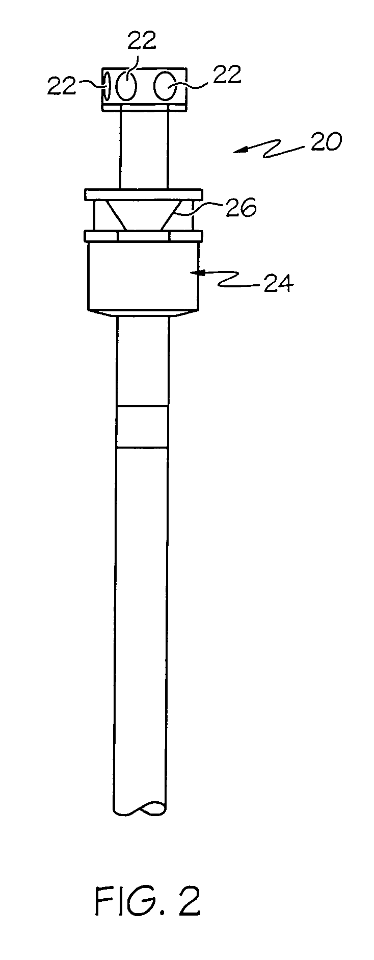
[0028]The electronic distance-measuring portion 16 transmits a beam of laser light through lens 18 toward a target 20. As seen in FIG. 2, target 20 inclu...


PUM


Abstract

A method of monitoring the location, and the orientation of a machine element, and apparatus for monitoring and controlling the operation of the machine include a robotic total station and a plurality of targets in known positions relative to the machine element. The total station, located at a known location near the machine element, repeatedly, successively determines the location of each target. Acquisition and re-acquisition of the targets is aided by stored data regarding the prior locations and movements of the targets. Further, active targets may be used to facilitate re-acquisition. The operation of the machine is controlled based upon the location and orientation of the machine element.

Description

CROSS-REFERENCE TO RELATED APPLICATIONS[0001]Not applicable.STATEMENT REGARDING FEDERALLY SPONSORED RESEARCH OR DEVELOPMENT[0002]Not applicableBACKGROUND OF THE INVENTION[0003]This invention relates generally to machine control methods and systems for machines having machine elements, such as for example construction machines such as graders, milling machines, pavers, and slip-forming machines. More particularly, the present invention relates to a machine control method and system using a stationary tracking station that determines the location and orientation of the machine element, and transmits this information to the machine for use in controlling the operation of the machine element.[0004]It is desirable to monitor the position and movement of various types of relatively slow-moving machines, such as for example construction machinery including graders, pavers, and slip-forming, as well as the position, orientation and movement of machine elements associated with such machines....

Claims


Application Information

Patent Timeline
Patent Type & Authority Patents(United States)
IPC IPC(8): G01C11/26G05B19/18
CPCE02F3/847E01C19/006
Inventor PIEKUTOWSKI, RICHARD PAUL
Owner TRIMBLE NAVIGATION LTD
Why Eureka
Try Eureka