Image forming apparatus

a technology of image forming apparatus and forming frame, which is applied in the direction of electrographic process apparatus, instruments, optics, etc., can solve the problems of increasing cost and increasing weight of the unit frame b>2/b>, and achieves the effect of speeding up image formation, not reducing cleaning properties, and increasing weigh

Inactive Publication Date: 2007-01-30
SEIKO EPSON CORP
View PDF12 Cites 0 Cited by
  • Summary
  • Abstract
  • Description
  • Claims
  • Application Information

AI Technical Summary

Benefits of technology

[0012]It is therefore an object of the present invention to provide an image forming apparatus which can enable to prevent the drive gear of the belt-shaped image bearing member unit from sinking in spite of the load variation thereby to prevent the variation of the speed of the belt, and to prevent deterioration of image quality by performing exact positioning in the up-and-down direction.

Problems solved by technology

Further, when the rigidity of the unit frame 2 increases to suppress the deformation of the unit frame 2, the weight of the unit frame 2 increases, which causes the increase of cost.

Method used


Image

  • Image forming apparatus
  • Image forming apparatus
  • Image forming apparatus

Examples


Embodiment Construction

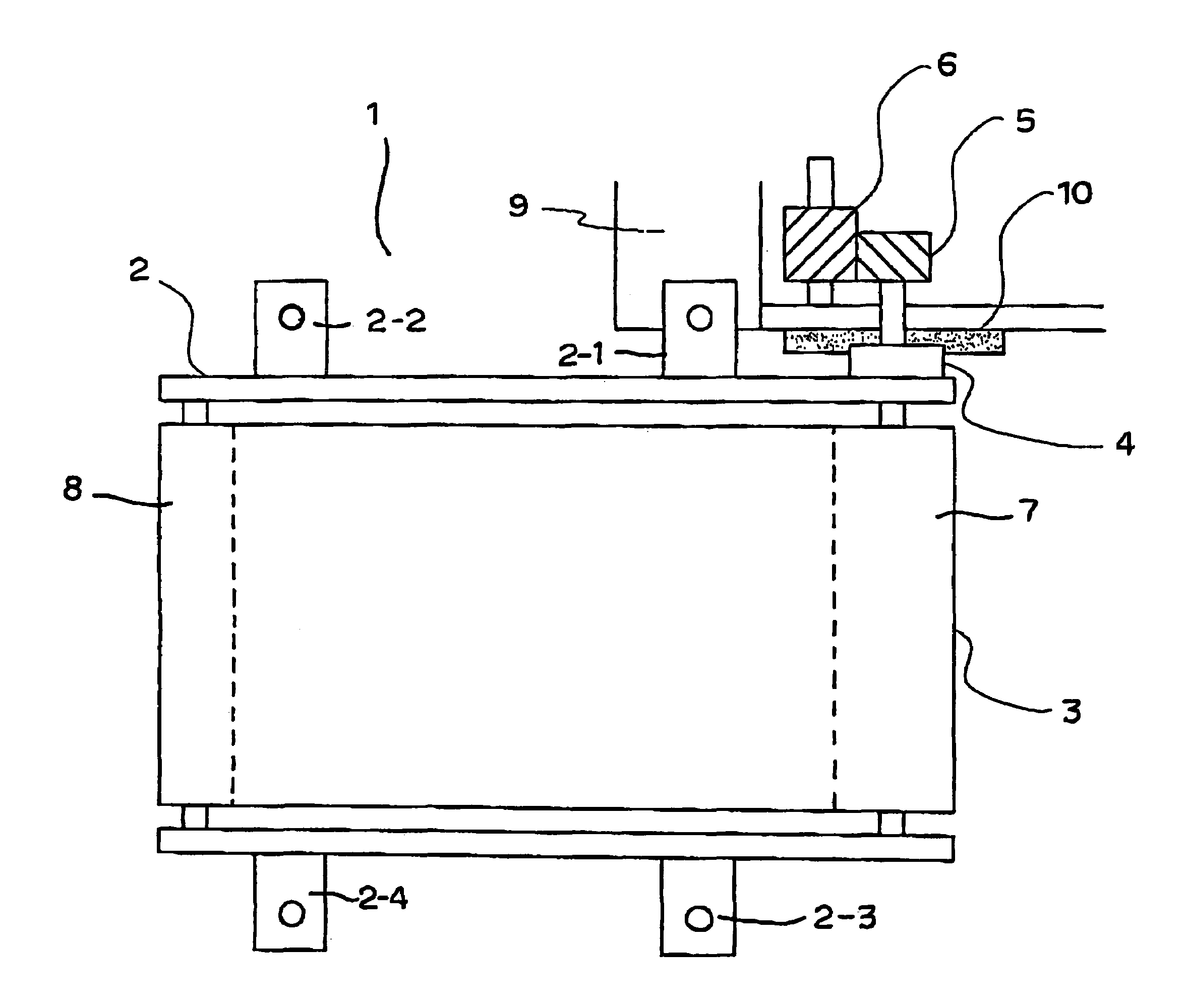
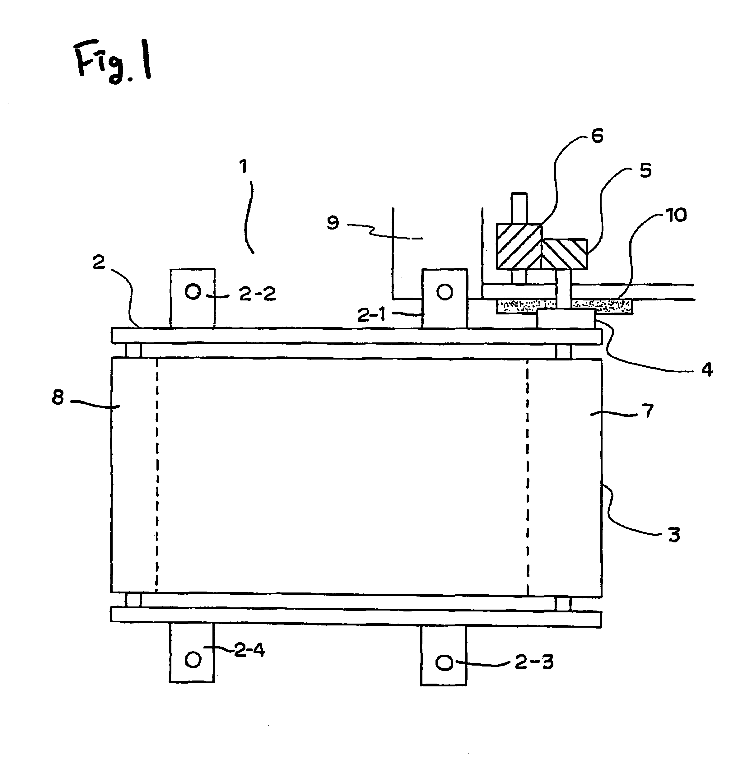
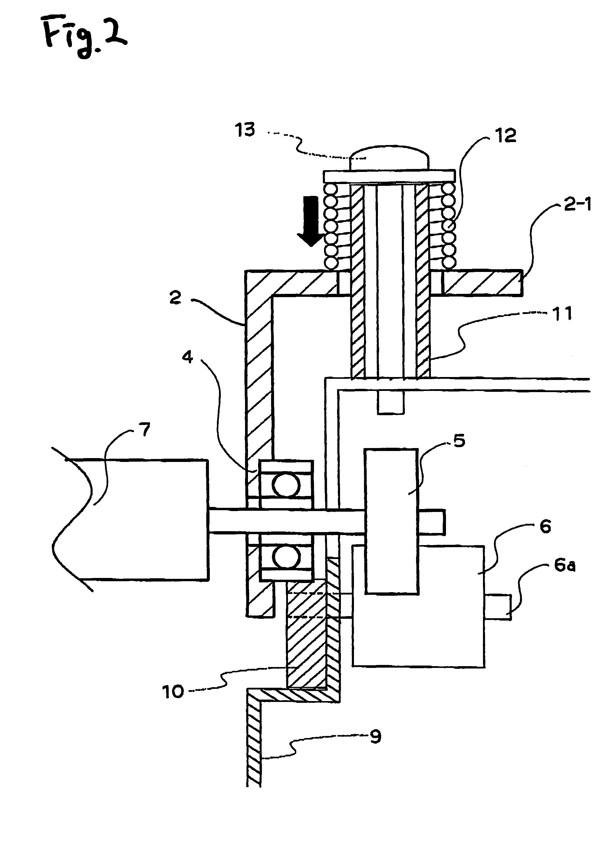
[0071]With reference to drawings, an embodiment of the invention will be described below. FIG. 1 is a diagram for explaining the embodiment of an image forming apparatus according to the invention, and FIG. 2 is a diagram showing a side section of a positioning part of an intermediate transfer unit to a body frame. In the figures, reference numeral 1 is an intermediate transfer unit, 2 is a unit frame, 2-1 to 2-4 are fixing legs, 3 is an intermediate transfer belt, 4 is a bearing, 5 is a drive gear, 6 is a drive transmitting gear, 7 is a drive roller, 8 is back up roller, 9 is a body frame, 10 is a positioning member, 11 is a bush, 12 is an energizing spring, 13 is a locking screw, and 14 is a cleaner blade.

[0072]in FIG. 1, the intermediate transfer unit i has the unit frame 2 which is formed both sides of the intermediate transfer belt 3 that is an image bearing member having an endless shaped belt, and the four going legs 2-1 to 2-4 protruding from the unit frame 2 are screwed to ...


PUM


Abstract

An image forming apparatus, includes an image bearing member having an endless belt shape, on which a toner image is formed, and the image bearing member, a drive roller, which rotates the image bearing member laid around the drive roller, a drive gear, which is connected to the drive roller, and a drive transmitting gear, which is engaged with the drive gear, and transmits a driving force to the drive gear to rotate the image bearing member. The drive transmitting gear is arranged so that a direction of a drive reaction force of the drive transmitting gear with respect to the drive gear substantially coincides with an ingress direction of the image bearing member toward the drive roller.

Description

BACKGROUND OF THE INVENTION[0001]The present invention relates to an image forming apparatus which includes a belt-shaped image bearing member unit that lays an image bearing member configured by an endless belt around a drive roller and a winding member to drive and rotate the image bearing member, and which forms a toner image on the image bearing member, and thereafter transfers the toner image onto a recording medium to form an image.[0002]In the image forming apparatus, a charging device for charging a photoconductor uniformly in a rotary direction, an exposing device for forming an eletrosatc latent image on the photoconductor, a developing device for developing the electrostatic latent image, a transferring device which transfers a toner image on the photoconductor onto a transfer medium, and a cleaner which cleans a face of the photoconductor after transfer, are arranged around the periphery of the photoconductor serving to an image bearing member. The electrostatic latent i...

Claims


Application Information

Patent Timeline
Patent Type & Authority Patents(United States)
IPC IPC(8): G03G15/00
CPCG03G15/757G03G2221/0005
Inventor MIZUSHIMA, NOBUYUKIFUJITA, SHIGEOTANAKA, KUNIAKIMIYAZAWA, HIROSHI
Owner SEIKO EPSON CORP
Why Eureka
Try Eureka