image forming device

An image and paper technology, applied in the field of image forming devices, can solve problems such as image scale changes, paper jams, and complicated roller drive control, and achieve the effect of preventing speed changes

Active Publication Date: 2019-10-29
ALPS ALPINE CO LTD
View PDF13 Cites 0 Cited by
  • Summary
  • Abstract
  • Description
  • Claims
  • Application Information

AI Technical Summary

Problems solved by technology

However, in such an image forming apparatus, it is difficult to set the timing when the paper is transferred from the paper feed roller to the conveying roller. Changes in the speed of the paper at the time of detachment, horizontal streaks in the image formed on the paper, changes in the scale of the image formed on the paper, etc.
[0011] However, in the image forming apparatus described in Patent Document 1, it is necessary to adjust the duty ratio of rotation and stop of the paper feed roller according to the rotation speed of the resist roller, so that the driving control of the roller becomes complicated.
[0012] The image forming apparatus described in Patent Document 2 needs a sensor for detecting the loaded amount of paper, and controls the operation of the transport roller based on the sensor output, so the control operation is still complicated.
[0013] The image forming apparatus described in Patent Document 3 requires a space for bending the paper and forming it into a loop between the paper feed roller and the conveyor belt, so the size of the apparatus is increased.
In addition, deflecting the paper is also likely to be the cause of paper jams
[0014] In addition, in the image forming apparatuses described in Patent Document 2 and Patent Document 3, the paper feed roller and the transport roller are arranged separately in the vertical direction, which is a direction intersecting with the paper feeding direction, so that the vertical dimension of the device becomes large, It is difficult to form a thin image forming device

Method used


Image

  • image forming device
  • image forming device
  • image forming device

Examples


Embodiment Construction

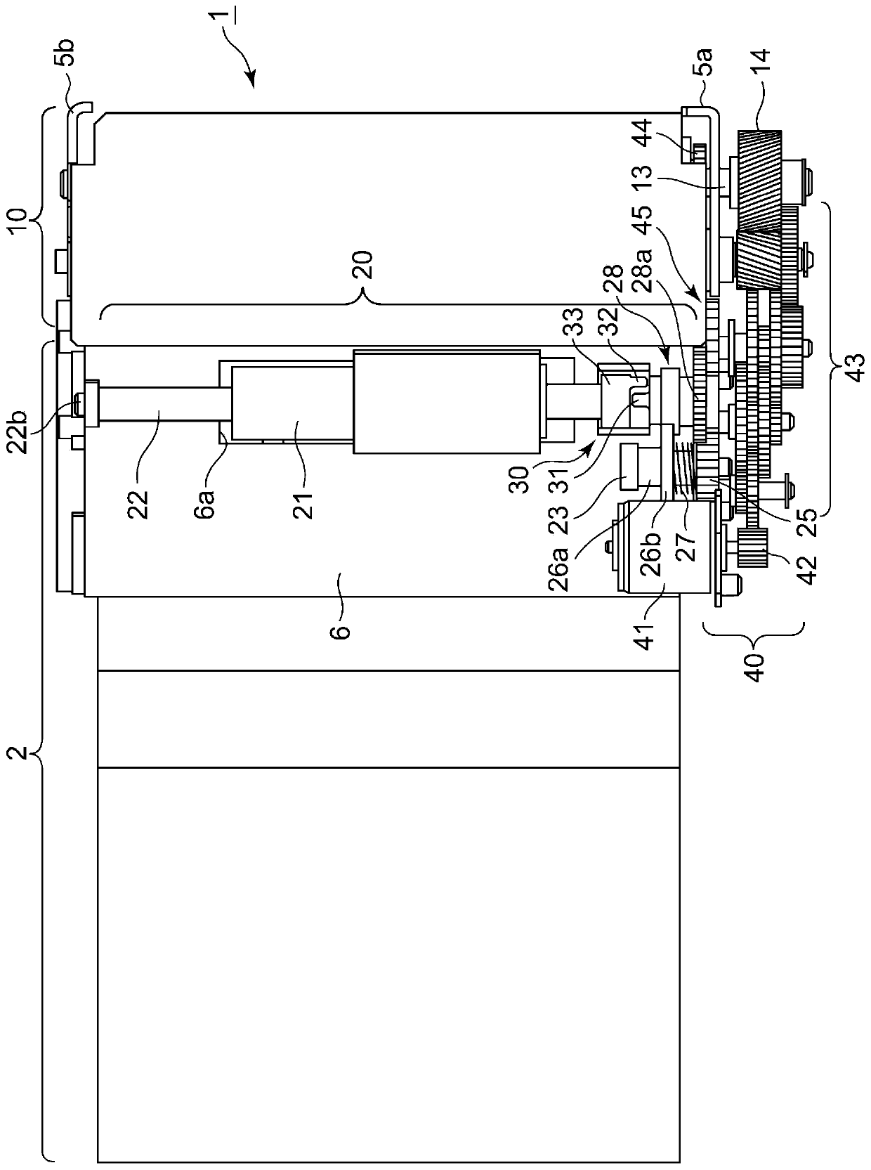
[0067] figure 1 It is a top view of the image forming apparatus 1. In the image forming apparatus 1, the paper setting section 2 and the image forming section 10 are arranged side by side, and are small and thin as a whole. The delivery mechanism section 20 is arranged to overlap the image forming section 10.

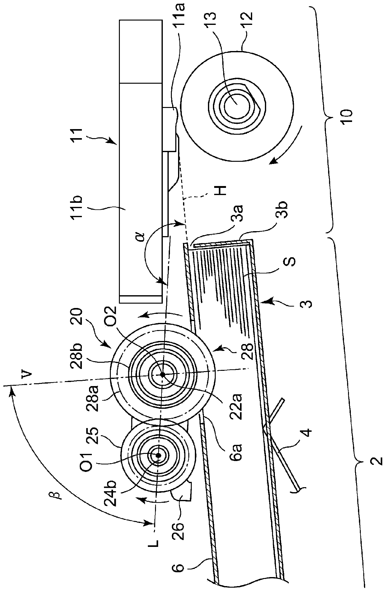
[0068] Such as image 3 with Figure 4 As shown, the paper feeding cassette 3 is installed in the paper setting part 2. One or more sheets of paper S are set (stored) inside the paper feed cassette 3. The paper setting part 2 is provided with an urging member 4 that pushes the paper S in the paper feed cassette 3 upward. in image 3 with Figure 4 In the example shown, the urging member 4 is a leaf spring. A paper feed slit 3a is formed in the upper part of the front of the paper feed cassette 3, and the uppermost paper of the paper S pushed up by the urging member 4 is sent out from the paper feed slit 3a.

[0069] In the image forming section 10, a printing member 11 i...


PUM


Abstract

The invention provides an image forming device which can deliver a sheet smoothly from a paper feed roller arranged on a sheet mounting part to a conveying roller arranged on an image forming part. A paper feed roller 21, which feeds a sheet S mounted on a sheet mounting part, rotates together with a swing gear 28a. A rotation center O2 of the swing gear 28a and the paper feed roller 21 is supported by a swing member 26. The swing member 26 swings with a rotation center O1 of a drive gear 25 as a fulcrum. When the drive gear 25 rotates in a clockwise direction, a moment M1 acts on the swing member 26, the paper feed roller 21 pressurizes a sheet S, and the sheet S is fed by rotation of the paper feed roller 21. When the sheet S is conveyed by the conveying roller of the image forming part, a speed of the sheet S is increased to a speed v2 so that a moment Mb in a clockwise direction acts on the swing member 26 and pressurizing force acting on the sheet S from the paper feed roller 21 reduces.

Description

Technical field [0001] The present invention relates to an image forming apparatus in which paper fed by a paper feed roller is transferred to a conveying roller to perform image printing, and more particularly to an image forming apparatus capable of smoothly transferring paper from the paper feed roller to the conveying roller. Background technique [0002] In the image forming apparatus, the paper is sent out from the paper setting section such as the paper feeding cassette by the paper feed roller, and the paper is transferred to the conveying roller such as the pressure roller provided in the image forming section. In the image forming section, the conveying speed of the conveying roller Synchronously form an image on the paper. However, in this type of image forming apparatus, it is difficult to set the timing when the paper is transferred from the paper feed roller to the conveying roller. For example, there is a problem that the rear end of the paper conveyed by the conve...

Claims


Application Information

Patent Timeline
Patent Type & Authority Patents(China)
IPC IPC(8): B41J13/00
Inventor 阿部荣文佐藤广志山本寿之竹内实
Owner ALPS ALPINE CO LTD
Why Eureka
Try Eureka