Remote control device

a remote control and control device technology, applied in the direction of process and machine control, toy aircraft, instruments, etc., can solve the problems of increasing the difficulty of maintaining a stable and constant flying speed of the helicopter, requiring a high level of skill, and the above-described operation assisting device is difficult for an operator to operate, so as to prevent unintentional speed changes, easily control a forward moving speed, and change the speed of transportation equipment.

Active Publication Date: 2016-11-24
YAMAHA MOTOR CO LTD
View PDF0 Cites 0 Cited by
  • Summary
  • Abstract
  • Description
  • Claims
  • Application Information

AI Technical Summary

Benefits of technology

[0012]Preferably, the instruction transmitter is movable from a baseline position. In this arrangement, the instruction transmitter is movable in a range which includes a speed determination range that outputs the speed determination signal from the instruction transmitter and a speed change range that outputs the speed change signal from the instruction transmitter. The speed determination range includes the baseline position, whereas the speed change range is outside of the speed determination range as viewed from the baseline position. With the above arrangement, the controller determines whether the speed of the transportation equipment should be maintained or brought to zero based on a result of comparison between speed information of the transportation equipment and the threshold value when the instruction transmitter is moved from the speed change range into the speed determination range. In this case, when the operator moves the instruction transmitter from the baseline position, passing through the speed determination range into the speed change range, then the speed of the transportation equipment is changed in accordance with the amount of operation applied to the instruction transmitter. Then, as the operator returns the instruction transmitter from the speed change range to the speed determination range (typically to the baseline position), the speed information of the transportation equipment at this time point is compared to the threshold value, and based on a comparison result, the speed of the transportation equipment is maintained or brought to zero. Such an arrangement, i.e., that the speed determination range is between the baseline position and the speed change range so that the instruction transmitter cannot reach the speed change range unless it is moved from the baseline position and through the speed determination range, makes the speed determination range function as a so-called “play” zone in relation to speed change operation of the transportation equipment. Therefore, it becomes possible to prevent unintentional speed changes of the transportation equipment which are not intended by the operator. This arrangement makes it possible to change the speed of the transportation equipment easily and only when the operator wants to do so.
[0013]Further preferably, the instruction transmitter is movable in both a positive direction and a negative direction from the baseline position. In this arrangement, the speed determination range includes the baseline position, and is on both the positive side and the negative side of the baseline position; the speed change range includes a first change range on the positive side of the baseline position and a second change range on the negative side of the baseline position outside of the speed determination range as viewed from the baseline position. With the above arrangement, the instruction transmitter outputs a speed change signal that accelerates the transportation equipment when the instruction transmitter is in the first change range, and the instruction transmitter outputs a speed change signal that decelerates the transportation equipment when the instruction transmitter is in the second change range. In this case, the first change range and the second change range are arranged in directions extending away from each other as viewed from the baseline position. This makes operations easy and clear when the operator accelerates or decelerates the transportation equipment using the instruction transmitter. It is possible to easily control a forward moving speed and a backward moving speed of the transportation equipment, and to significantly reduce or prevent undesired or unintended operations.
[0014]Further, preferably, the instruction transmitter includes a stick-shaped member (e.g., joystick) which returns to the baseline position unless a force is applied, and an operation angle of the joystick represents an amount of operation applied to the instruction transmitter. In this case, when the operator tilts the joystick from the baseline position, passing through the speed determination range into the speed change range, then the speed of the transportation equipment is changed in accordance with the operation angle of the joystick. Then, as the operator returns the joystick from the speed change range to the speed determination range, the speed information of the transportation equipment at this time point is compared to the threshold value, and based on a comparison result, the speed of the transportation equipment is maintained or brought to zero. In other words, if an absolute value of the speed information of the transportation equipment is not smaller than the threshold value (greater than the threshold value), control is performed to maintain the speed of the transportation equipment. On the other hand, if the absolute value of the speed information of the transportation equipment is smaller than the threshold value (not greater than the threshold value), control is performed to bring the speed of the transportation equipment to zero (and then maintain that speed thereafter). It is possible to maintain the transportation equipment at a desired speed easily by simply operating the joystick thus changing the output from the instruction transmitter from the speed change signal to the speed determination signal. Also, the joystick returns to the baseline position if no force is applied. Therefore, the operator should apply a force to tilt the joystick only when accelerating or decelerating the transportation equipment, and there is no need to operate the joystick to maintain the speed of the transportation equipment. This makes operation of the instruction transmitter easy. Further, since the joystick returns to the baseline position if there is no operation being made to the joystick, it is possible to prevent undesired acceleration and deceleration of the transportation equipment.

Problems solved by technology

However, if a desired flying speed is to be maintained at a constant level, the above-described operation assisting device is difficult for an operator to operate and requires a high level of skill.
In particular, under external conditions such as strong winds, it becomes even more difficult to maintain a stable and constant flying speed of the helicopter.

Method used


Image

  • Remote control device
  • Remote control device
  • Remote control device

Examples


Embodiment Construction

[0023]Hereinafter, preferred embodiments of the present invention will be described with reference to the drawings.

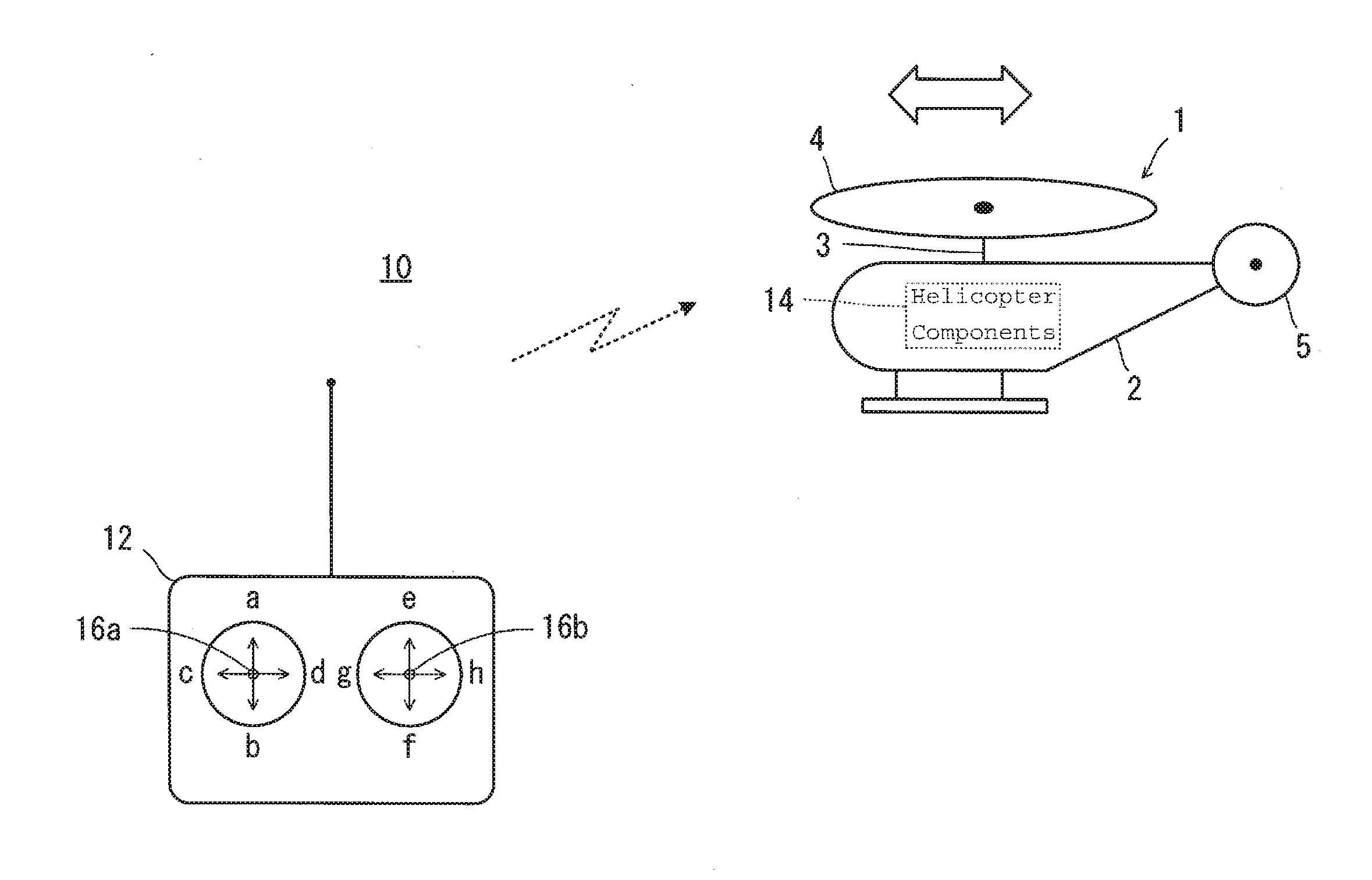
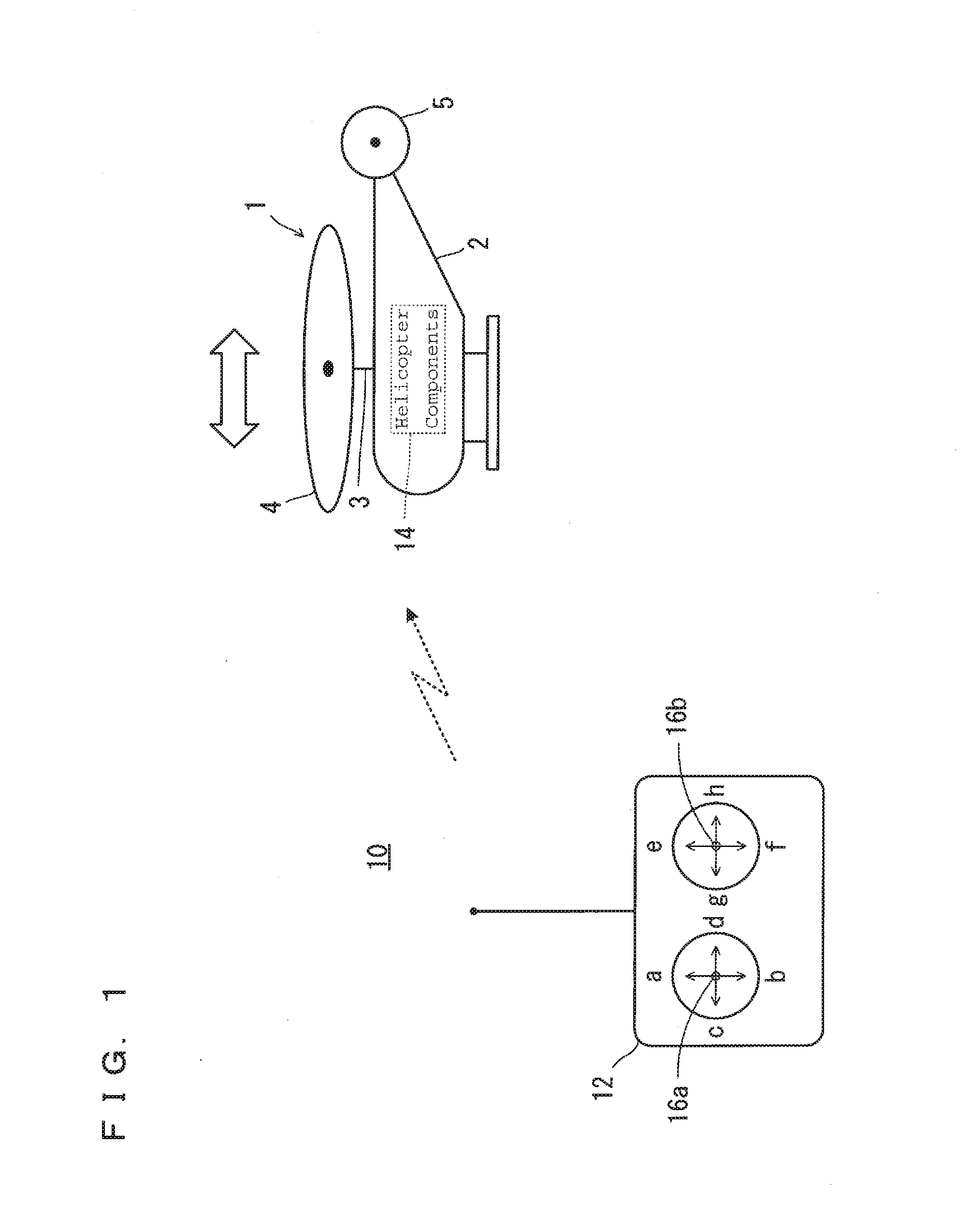
[0024]In a preferred embodiment of the present invention shown in FIG. 1, a transportation equipment preferably is, for example, an unmanned helicopter 1 (hereinafter, simplified as helicopter 1). Therefore, a remote control device 10 according to the preferred embodiment shown in FIG. 1 is a remote control device for the helicopter 1.

[0025]The helicopter 1 includes a body 2, a mast 3, a main rotor 4, and a tail rotor 5. The mast 3 protrudes upward from the body 2 and is rotatable. The mast 3 includes an upper end portion where the main rotor 4 is fixed. The tail rotor 5 is rotatable and is located at a rear end portion of the body 2. The main rotor 4 and the tail rotor 5 are rotated based on a driving force from an unillustrated drive source.

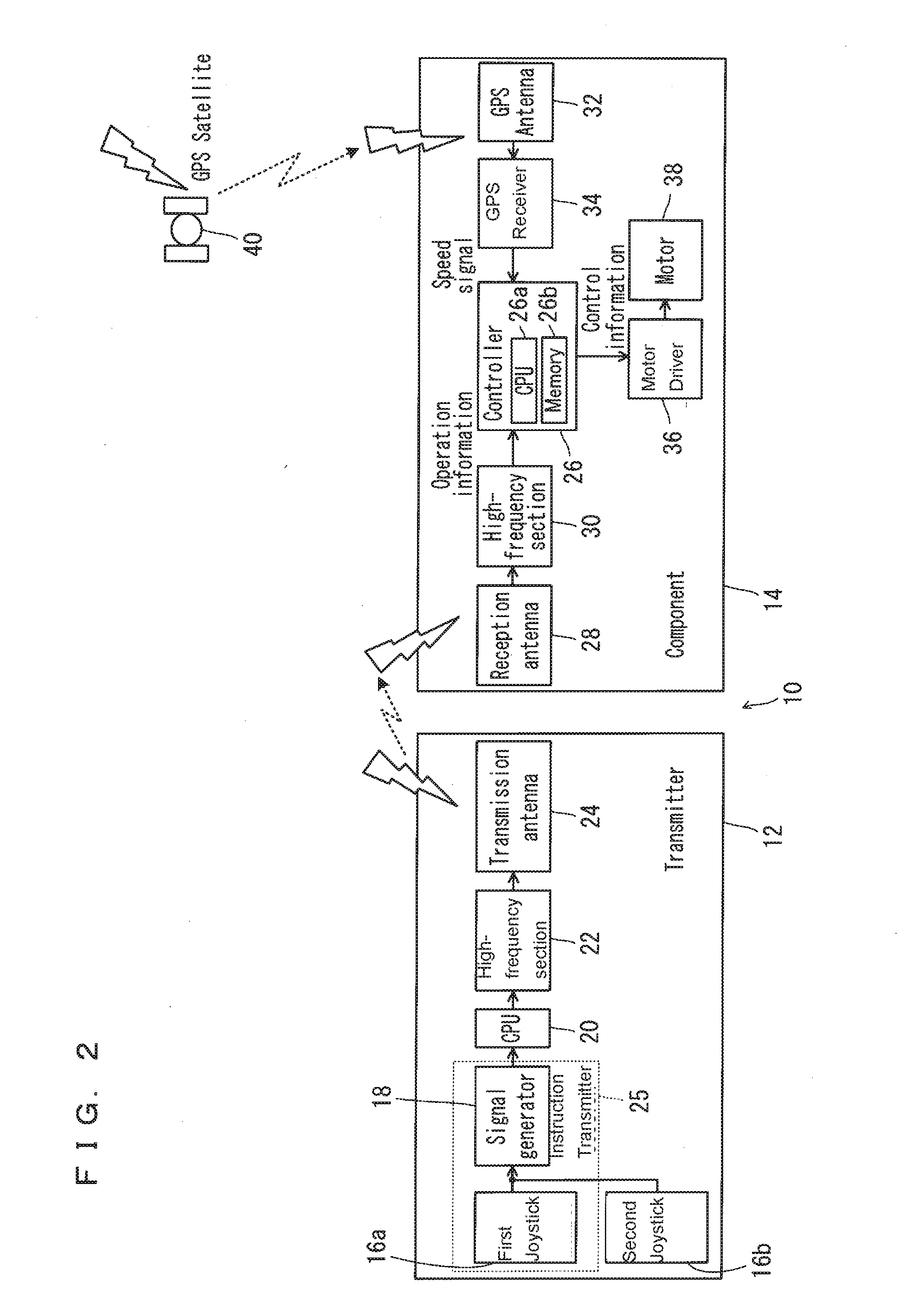
[0026]The remote control device 10 includes a transmitter 12 which transmits signals toward the helicopter 1, and helicopter comp...


PUM


Abstract

A remote control device includes an instruction transmitter and a controller which controls a speed of an unmanned helicopter based on an instruction from the instruction transmitter. The instruction transmitter selectively outputs one of a speed change signal that changes the speed of the unmanned helicopter and a speed determination signal that determines the speed of the unmanned helicopter. When an output from the instruction transmitter is changed from the speed change signal to the speed determination signal, the controller determines whether the speed of the unmanned helicopter should be maintained or brought to zero based on a result of comparison between speed information of the unmanned helicopter and a threshold value. Preferably, the speed change signal changes the speed of the unmanned helicopter by changing a tilt angle of a nose of the unmanned helicopter in an up-down direction in accordance with an amount of operation applied to the instruction transmitter.

Description

BACKGROUND OF THE INVENTION[0001]1. Field of the Invention[0002]The present invention relates to remote control devices, and more specifically to a remote control device which is used to control transportation equipment such as an unmanned helicopter.[0003]2. Description of the Related Art[0004]An example of a conventional technique of this kind is disclosed in JP-A 2009-96369.[0005]JP-A 2009-96369 discloses an operation assisting device for an unmanned radio-controlled helicopter. The operation assisting device is interposed between a receiver and servo motors in a conventional unmanned radio-controlled helicopter, and includes a microcomputer, a PWM signal reading circuit, a PWM signal generation circuit, a PWM signal switching circuit, and various sensors. With the arrangement described above, hovering is performed when the operator's operation is in neutral, and when there is an operation by the operator, the servo motors are controlled accordingly or an amount of the operation ...

Claims


Application Information

Patent Timeline
Patent Type & Authority Applications(United States)
IPC IPC(8): G05D13/04G05D1/00B64C39/02G05D1/02
CPCG05D13/04G05D1/0202B64C2201/024B64C39/024G05D1/0016A63H27/12A63H30/04G05D1/0033B64U10/10B64U2201/20
Inventor ADACHI, HAJIME
Owner YAMAHA MOTOR CO LTD
Why Eureka
Try Eureka