Control system for variable valve timing apparatus

a variable valve timing and control system technology, applied in mechanical equipment, valve arrangements, machines/engines, etc., can solve the problems of not considering the output torque of the electric motor, the output torque of the variable valve timing apparatus may not be driven, and the inability to so as to reduce the operating sound of the vvt apparatus and accurately reflect the load torque

Active Publication Date: 2014-03-13
DENSO CORP
View PDF5 Cites 2 Cited by
  • Summary
  • Abstract
  • Description
  • Claims
  • Application Information

AI Technical Summary

Benefits of technology

[0009]According to the above feature, the power supply increase control is carried out when changing (advancing or retarding) the rotational phase of the cam shaft during the engine operation is stopped, so that the power supply to the electric motor is increased to the power increase amount at the beginning of the power supply to the electric motor. As a result, the output torque of the electric motor can be properly increased to drive the VVT apparatus, and thereby the cam shaft phase can be surely changed. The power increase amount corresponds to such a power supply amount, with which a torque necessary for driving the VVT apparatus (that is, a torque necessary for overcoming the static friction forces of respective portions of the VVT apparatus) during the engine operation is stopped. For example, such power supply amount corresponds to a duty ratio higher than a ratio of 80%, which is larger than a power-supply duty ratio (that is, a power holding duty ratio) necessary for keeping the cam shaft phase at a constant value during the engine is operated.
[0010]In addition, after the above power supply increase control, the feedback control is carried out for the power supply to the electric motor, so that the actual changing speed of the rotational phase of the cam shaft is controlled to be equal to the target changing speed. Accordingly, the changing speed of the cam shaft phase is prevented from becoming too fast and the operating sound of the VVT apparatus can be decreased.
[0011]When, the cam shaft phase is changed, a load torque for compressing a valve spring of an intake valve or an exhaust valve becomes larger, while the load torque becomes smaller in the case that the valve spring is expanded. Therefore, since the actual changing speed of the cam shaft phase varies depending on the load torque of the VVT apparatus during its power supply increase control, the actual changing speed of the cam shaft phase during the power supply increase control is one of parameters which accurately reflect the load torque of the VVT apparatus.
[0014]When the cam shaft phase is changed during the engine operation is stopped, the load torque for the VVT apparatus may easily vary and the changing speed of the cam shaft phase may easily vary. Therefore, according to a further feature of the invention, during the feedback control for the changing speed of the rotational phase, the power supply amount may be feedback controlled by use of an integral term. According to such feature, it is possible to effectively reduce a deviation between the actual changing speed and the target changing speed of the cam shaft phase during the feedback control, and thereby to stabilize the actual changing speed of the cam shaft phase.

Problems solved by technology

However, the necessary output torque is not considered in the above mentioned prior art (JP Patent No. 4,267,635).
It may happen that the output torque of the electric motor may come short and thereby the variable valve timing apparatus may not be driven.
As a result, it may happen that the cam shaft phase may not be changed.

Method used


Image

  • Control system for variable valve timing apparatus
  • Control system for variable valve timing apparatus
  • Control system for variable valve timing apparatus

Examples


first embodiment

[0032]Embodiments of the present invention will be explained with reference to the embodiments shown in the drawings, wherein the present invention is applied to a variable valve timing apparatus for an intake valve.

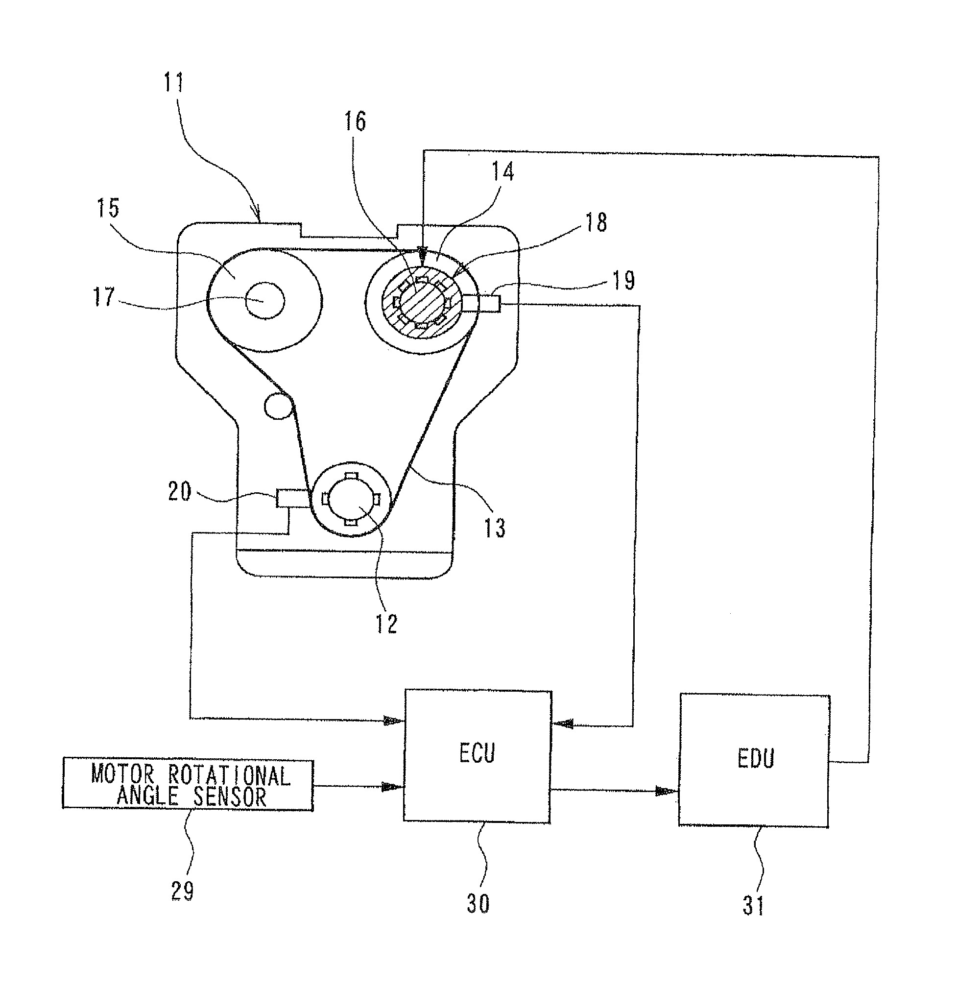
[0033]At first, an entire structure for a variable valve timing control system will be explained with reference to FIG. 1.

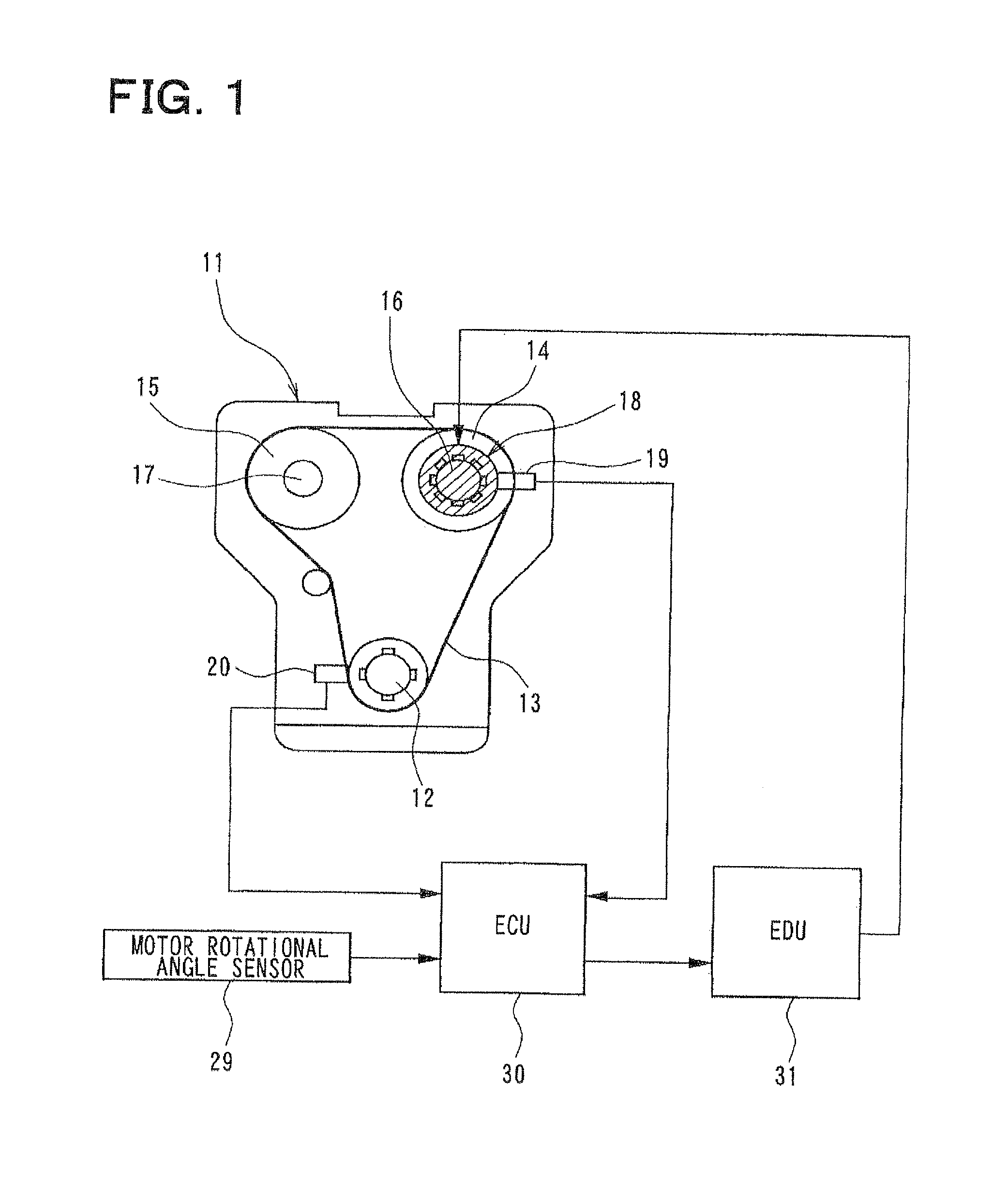
[0034]A driving power of an internal combustion engine 11 is transmitted by a timing chain (or a timing belt) 13 from a crank shaft 12 to a cam shaft 16 for an intake valve as well as to a cam shaft 17 for an exhaust valve via respective sprockets 14 and 15. A variable valve timing (VVT) apparatus 18 of an electrically-driven type is provided at the cam shaft 16 for the intake valve. A rotational phase (a cam shaft phase) of the cam shaft 16 with respect to the crank shaft 12 is changed by the variable valve timing (VVT) apparatus 18, so that a valve timing (a valve opening timing and / or a valve closing timing) for the intake valve (not shown), which ...

second embodiment

[0076]A second embodiment of the present invention may be applied to the VVT control system shown in FIGS. 1 and 2. Therefore, the second embodiment will be explained with reference to FIGS. 1, 2 and 6A to 8.

[0077]An optimum value of the valve timing at starting the engine depends on temperature of the engine 11 (temperature of engine cooling water). More exactly, the optimum value of the valve timing is shifted to an advancing side, as the temperature of the engine cooling water becomes lower. When the engine operation is stopped by turning off the ignition switch, and if the valve timing is not set at a proper value for a next engine starting operation (wherein the proper value depends on the temperature of the engine cooling water at re-starting the engine operation), it may happen that the engine operation may not be smoothly started.

[0078]According to the second embodiment, the valve timing is changed not only during the engine is operated but also when the engine operation is ...


PUM


Abstract

When a cam shaft phase is changed during engine operation is stopped, a power supply increase control to an electric motor is carried out, according to which a power-supply duty ratio to the electric motor is increased to a predetermined power increase value which is necessary for moving a VVT apparatus during the stop of the engine operation. Then, the power-supply duty ratio is feedback controlled so that an actual changing speed of the cam shaft phase becomes equal to a target changing speed. As a result, the cam shaft phase can be surely changed and operating sound can be reduced by preventing the changing speed of the cam shaft phase from becoming too fast.

Description

CROSS REFERENCE TO RELATED APPLICATION[0001]This application is a divisional of U.S. application Ser. No. 12 / 917,663, filed Nov. 2, 2010, which is based on Japanese Patent Application No. 2009-251708 filed on Nov. 2, 2009 and No. 2010-000944 filed on Jan. 6, 2010, the disclosures of each of which are incorporated herein by reference.FIELD OF THE INVENTION[0002]The present invention relates to a variable valve timing apparatus of an electrically-driven type, more particularly to a control system for such variable valve timing apparatus, according to which a rotational phase of a cam shaft with respect to a crank shaft of an internal combustion engine is changed by an electric motor in order to change valve timing.BACKGROUND OF THE INVENTION[0003]Conventionally, a variable valve timing apparatus is known in the art, which is mounted in an internal combustion engine for a vehicle, and according to which a valve timing (a valve opening and / or valve closing timing) for an intake valve an...

Claims


Application Information

Patent Timeline
Patent Type & Authority Applications(United States)
IPC IPC(8): F01L1/344
CPCF01L1/344F01L1/022F01L1/024F01L1/352F01L2001/0537F01L2800/01F01L2800/03
Inventor HIRATA, YASUO
Owner DENSO CORP
Why Eureka
Try Eureka