
Non clogging screen

a technology of clogging screen and perforation surface, which is applied in the direction of filtering separation, cartridge filter, separation process, etc., can solve the problems of lack of effective downward extending water channeling paths, and achieve the effect of reducing cost to manufacturer and consumer

Inactive Publication Date: 2007-02-13
MGP MFG
View PDF50 Cites 75 Cited by
  • Summary
  • Abstract
  • Description
  • Claims
  • Application Information

AI Technical Summary

Benefits of technology

The solution effectively channels rainwater into the gutter while preventing debris and pollutants from entering, maintaining water permeability and self-cleaning capabilities, even under heavy rainfall, and is more cost-effective to manufacture than similar efficient systems like LEAFFILTER™.

Problems solved by technology

The absence of effective downward extending water channeling paths exhibited in prior art that employs filtering methods often allows for the forward channeling of water past rather than downward into an underlying rain gutter.

Method used


Image

  • Non clogging screen
  • Non clogging screen
  • Non clogging screen

Examples


Embodiment Construction

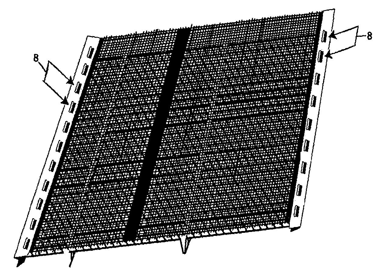
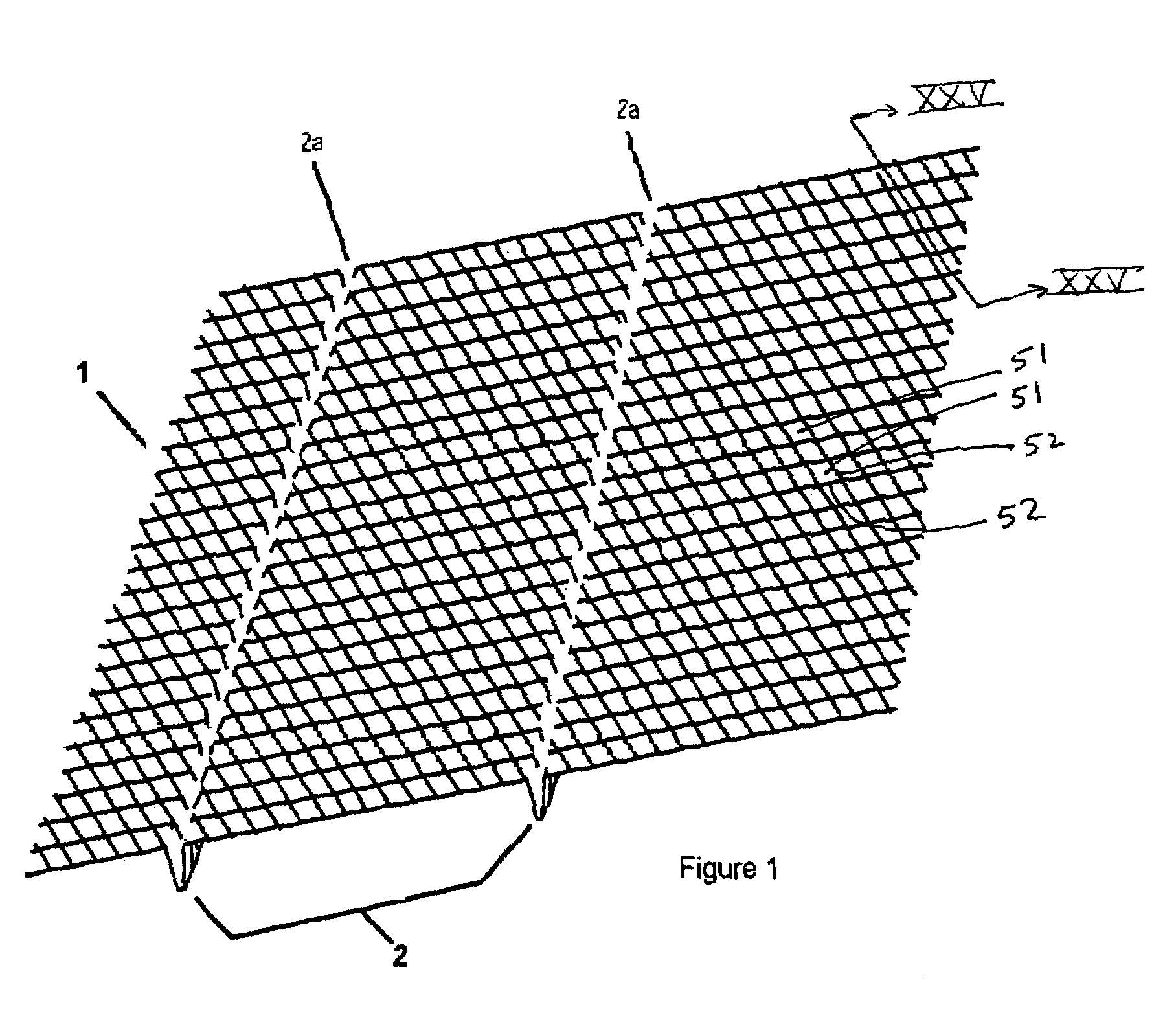
[0067]Referring now specifically to the drawings, in FIG. 1 a gutter screen (protector) is illustrated 1 with downward extending water receiving channels 2. The preferred gauge of the gutter screen wire is approximately 0.035 to 0.055 inch, which is suitably thick to maintain it's shape and not deform or dip under load bearing weight of snow and ice. The preferred gauge of the gutter screen wire is also of a narrow enough diameter (0.035 to 0.055) to allow the screen 1 sufficient flexibility to be wrapped around a spindle 25 and later unrolled in a manufacturing process as illustrated in FIG. 19.

[0068]Referring now to FIG. 1 the gutter screen 1 presents a horizontal surface which extrudes downward into channels 2, which act to inhibit the forward flow of rainwater off a roof structure by means of their open-air areas 2a, having no greater than ¼ inch width of open air, which interrupt or inhibit some amount of forward water flow. The forward flow of water is further inhibited by bei...


PUM

PropertyMeasurementUnit
heightaaaaaaaaaa
widthsaaaaaaaaaa
lengthaaaaaaaaaa

Abstract

A filter assembly is provided that has a filtering screen and a skeletal structure, the skeletal structure being attached to the filtering screen. At least one of the filtering screen and the skeletal structure form a plurality of downward extending channels.

Description

[0001]This application is a continuation of U.S. patent application Ser. No. 10 / 635,679, entitled “Non Clogging Screen,” filed Aug. 7, 2003, now U.S. Pat. No. 6,951,077, issued Oct. 4, 2005, the entirety of which is incorporated herein by reference, and claims priority to Provisional Patent Application Ser. No. 60 / 401,781 filed Aug. 8, 2002.BACKGROUND OF THE INVENTION[0002]1. Field of the Invention[0003]The invention relates to composite screen or perforated surface and filtering membranes.[0004]2. Related Prior Art[0005]Various gutter anti-clogging devices are known in the art and some are described in issued patents.[0006]In my U.S. Pat. No. 6,598,352, incorporated herein by reference, I disclose a filter configuration comprised of a debris repelling membrane, overlying a skeletal structure of ellipsoid rods spaced and resting on vertical planes that serve to break the forward flow of water and to channel water onto and through its integral perforated horizontal plane. Included he...

Claims


Application Information

Patent Timeline
Patent Type & Authority Patents(United States)
IPC IPC(8): E04C2/42E04C5/04E04D13/00E04D13/076
CPCE04D13/076
Inventor HIGGINBOTHAM, EDWARD A.
Owner MGP MFG
Learn More