Insertion tube methods and apparatus

a technology of insertion tube and tube body, which is applied in the direction of surveying, instruments, borehole/well accessories, etc., can solve the problems of difficult remediation and containment efforts, inability to place probes into the subsurface for data collection in such sites, and high cos

Inactive Publication Date: 2007-02-20
BATTELLE ENERGY ALLIANCE LLC
View PDF33 Cites 16 Cited by
  • Summary
  • Abstract
  • Description
  • Claims
  • Application Information

AI Technical Summary

Problems solved by technology

However, as described above, placing probes into the subsurface for data collection in such sites has not been feasible, because the placing of such probes would require drilling or coring which would bring contaminated “cuttings” to the surface and would create a pathway through which contaminated emissions may escape.
Unfortunately, such probe placement only provides information when the contaminants have already migrated outside of the waste disposal site area.
Moreover, at the point when the contaminants have already migrated outside of the waste disposal site area, it is likely that a major contaminant plume already exists in the subsurface soil and aquifer making remediation and containment efforts much more difficult and costly.

Method used


Image

  • Insertion tube methods and apparatus
  • Insertion tube methods and apparatus
  • Insertion tube methods and apparatus

Examples


Embodiment Construction

[0016]This disclosure of the invention is submitted in furtherance of the constitutional purposes of the U.S. Patent Laws “to promote the progress of science and useful arts” (Article 1, Section 8).

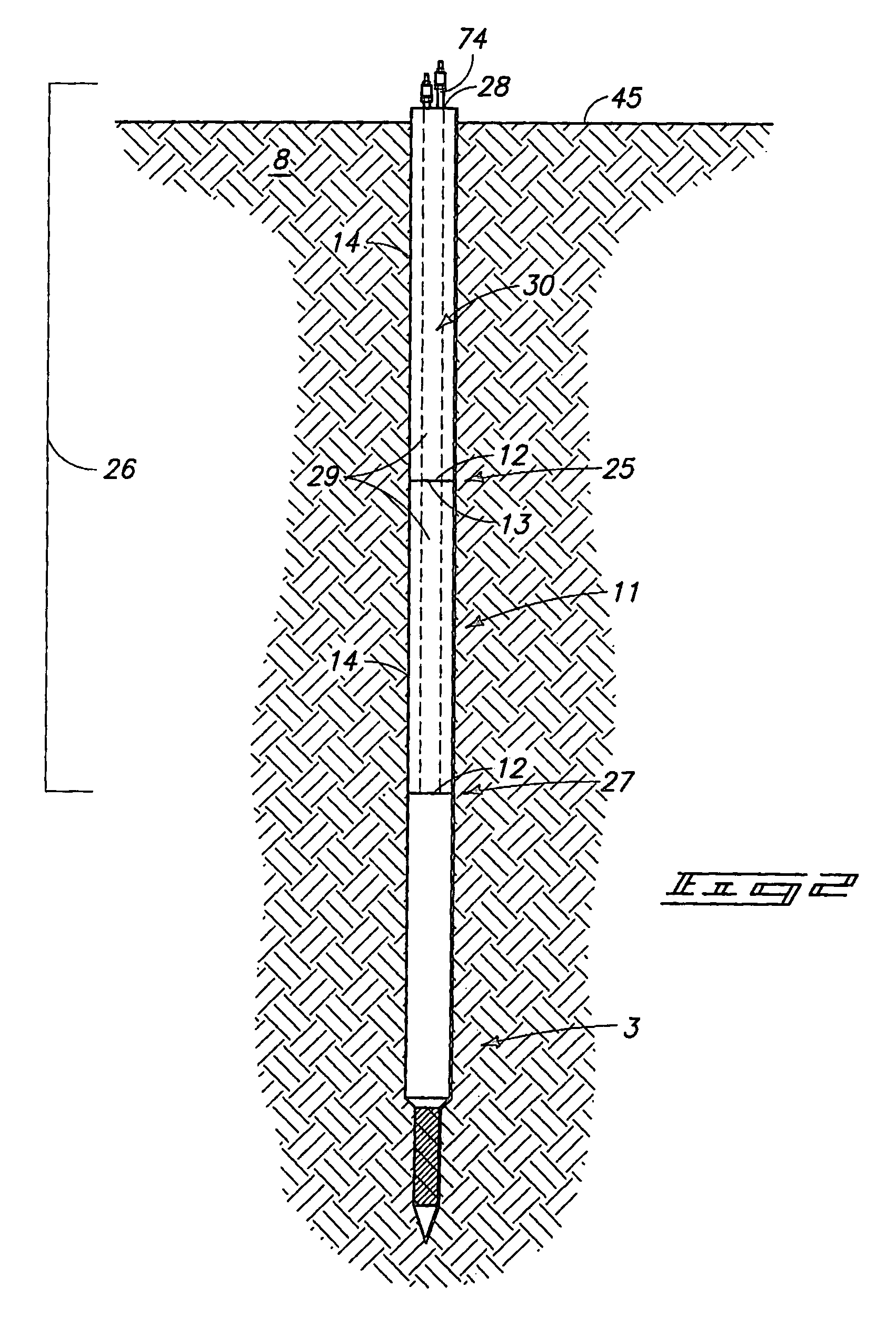
[0017]The invention relates to methods and apparatus for subsurface testing. More specifically, the invention relates to methods and apparatus for placing instrumented probes into a substrate. The invention allows such placement to be carried out in either contaminated or non-contaminated sites without the need for drilling or coring. In one implementation, the method includes placing an instrumented probe into the substrate using direct push, sonic drilling, or a combination of direct push and sonic drilling.

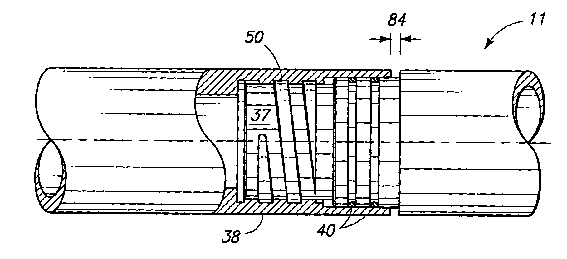
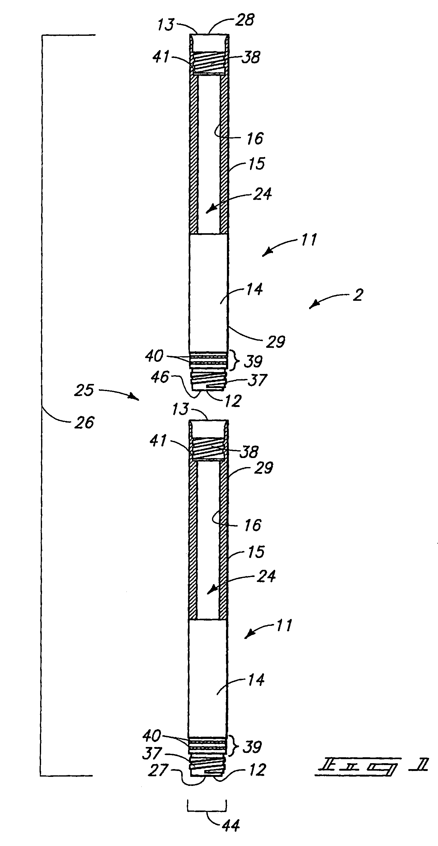
[0018]Shown in the various drawings is an apparatus 2 which facilitates placing an instrumented probe into a sample or the earth (hereinafter “the ground”) 8 (FIGS. 2 and 3). The apparatus 2 may be used to facilitate the placement of a variety of instrumented probes 3 into the ground...


PUM

PropertyMeasurementUnit
depthaaaaaaaaaa
thicknessaaaaaaaaaa
length L1aaaaaaaaaa

Abstract

A drill string comprises a first drill string member having a male end; and a second drill string member having a female end configured to be joined to the male end of the first drill string member, the male end having a threaded portion including generally square threads, the male end having a non-threaded extension portion coaxial with the threaded portion, and the male end further having a bearing surface, the female end having a female threaded portion having corresponding female threads, the female end having a non-threaded extension portion coaxial with the female threaded portion, and the female end having a bearing surface. Installation methods, including methods of installing instrumented probes are also provided.

Description

RELATED APPLICATIONS[0001]This is a Continuation-in-Part of U.S. patent application Ser. No. 10 / 910,860, filed Aug. 3, 2004 now abandoned, which in turn is a Divisional of U.S. application Ser. No. 10 / 285,786, filed Oct. 31, 2002 now abandoned, by William L. Casper, et al., entitled “Insertion Tube Methods and Apparatus”.GOVERNMENT RIGHTS[0002]The United States Government has certain rights in this invention pursuant to Contract No. DE-AC07-99ID13727, and Contract No. DE-AC07-05ID14517 between the United States Department of Energy and Battelle Energy Alliance, LLC.TECHNICAL FIELD[0003]The invention relates to methods and apparatus for subsurface testing. More specifically the invention relates to methods and apparatus for placing instrumented probes into the ground.BACKGROUND OF THE INVENTION[0004]Water and associated contaminants seep into the ground and travel through a subsurface region known as the vadose zone (a region of unsaturated soil). How the water and associated contami...

Claims


Application Information

Patent Timeline
Patent Type & Authority Patents(United States)
IPC IPC(8): G01N1/26E21B49/08F16L25/14G01L7/18
CPCE21B17/042E21B49/00F16L15/007F16L15/08F16L15/009F16L15/04F16L15/008
Inventor CASPER, LEGAL REPRESENTATIVE, CHRISCLARK, DON T.GROVER, BLAIR K.MATHEWSON, RODNEY O.SEYMOUR, CRAIG A.CASPER, DECEASED, WILLIAM L.
Owner BATTELLE ENERGY ALLIANCE LLC
Why Eureka
Try Eureka