Control system of internal combustion engine

a control system and internal combustion engine technology, applied in the direction of electrical control, process and machine control, instruments, etc., can solve the problems of large control load at the time of map searching, enormous manhours involved in mapmaking work, etc., to achieve accurate detection of the pressure of the intake pipe on the downstream side, simplified steady operation, and reduced control load

Active Publication Date: 2007-02-20
TOYOTA JIDOSHA KK
View PDF25 Cites 7 Cited by
  • Summary
  • Abstract
  • Description
  • Claims
  • Application Information

AI Technical Summary

Benefits of technology

[0015]According to the present embodiment, it is possible to more simply find the downstream side intake pipe pressure and / or cylinder intake air flow at the time of steady operation.
[0034]According to the present embodiment, the calculation when finding the downstream side intake pipe pressure and / or cylinder intake air flow at the time of steady operation is simplified and the control load can be reduced. Further, by considering the pressure loss of the air cleaner etc., it is possible to more accurately find the downstream side intake pipe pressure and / or cylinder intake air flow at the time of steady operation.

Problems solved by technology

The downstream side intake pipe pressure at the time of steady operation had in the past been found using a map, but there were the problems that the manhours involved in mapmaking work was tremendous and the control load at the time of map searching was also large.

Method used


Image

  • Control system of internal combustion engine
  • Control system of internal combustion engine
  • Control system of internal combustion engine

Examples


Embodiment Construction

[0051]Below, embodiments of the present invention will be explained in detail with reference to the drawings. Note that in the figures, the same or similar elements are assigned common reference numerals.

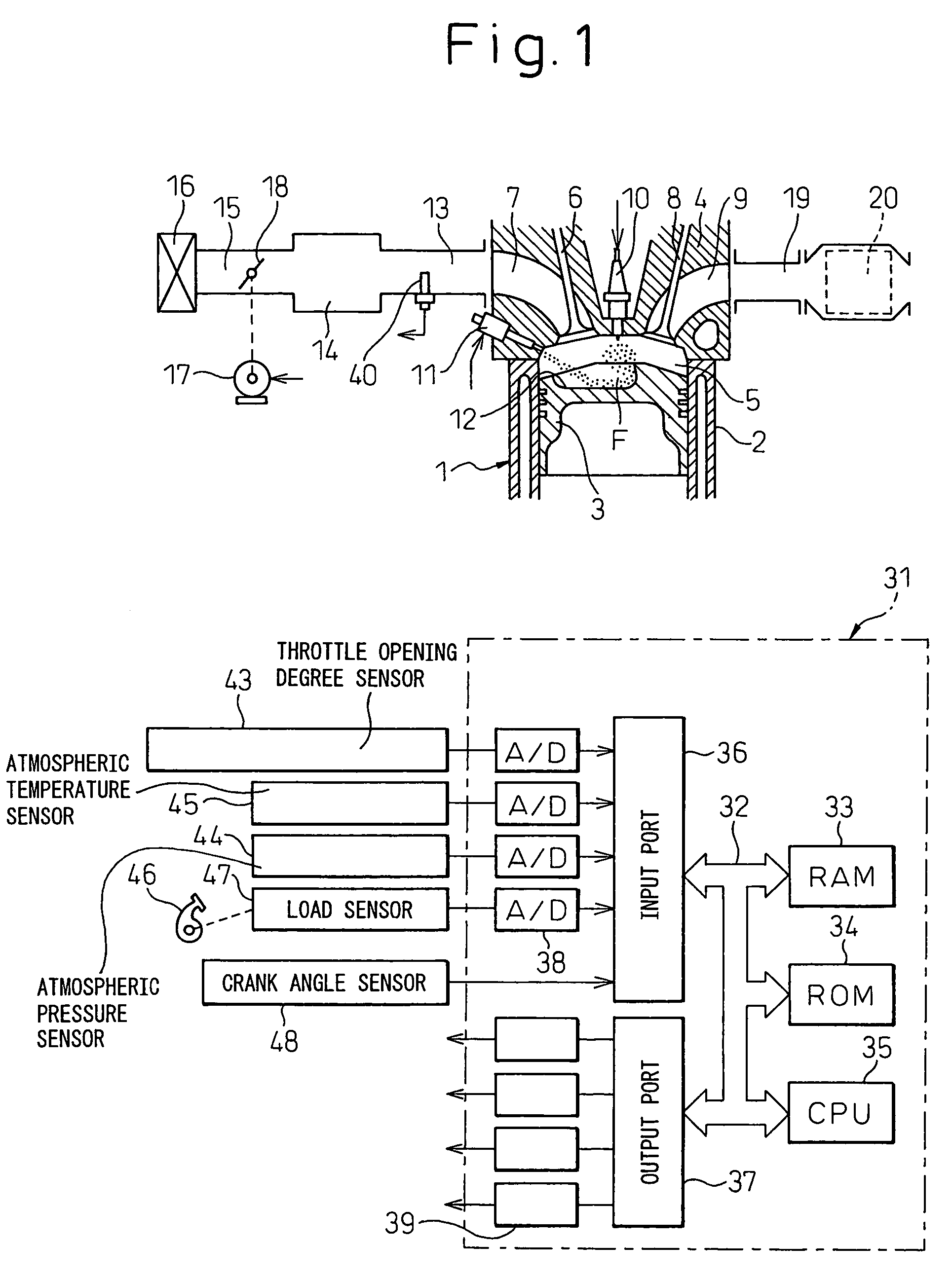
[0052]FIG. 1 is a schematic view showing an example of the case of applying a control system of an internal combustion engine of the present invention to a cylinder injection type spark ignition internal combustion engine. Note that the present invention may also be applied to another spark ignition type internal combustion engine or compression ignition type internal combustion engine.

[0053]As shown in FIG. 1, an engine body 1 is provided with a cylinder block 2, pistons 3 reciprocating inside the cylinder block 2, and a cylinder head 4 fixed on the cylinder block 2. The pistons 3 and cylinder head 4 form combustion chambers 5 between them. The cylinder head 4 is provided with, for each cylinder, intake valves 6, intake ports 7, exhaust valves 8, and exhaust ports 9. Further, as sh...


PUM


Abstract

A control system of an internal combustion engine provided with a throttle valve passage air flow calculation equation by which the throttle valve passage air flow mt is expressed as a function of the downstream side intake pipe pressure at the downstream side of the throttle valve and a cylinder intake air flow calculation equation by which the cylinder intake air flow mc is expressed as a function of the downstream side intake pipe pressure, where said downstream side intake pipe pressure Pm and cylinder intake air flow mc when the throttle valve passage air flow mt found from said throttle valve passage air flow calculation equation and the cylinder intake air flow mc found from said cylinder intake air flow calculation equation match are calculated as the downstream side intake pipe pressure Pmta and cylinder intake air flow mcta at the time of steady operation under the operating conditions at that time is provided.

Description

TECHNICAL FIELD[0001]The present invention relates to a control system of an internal combustion engine.BACKGROUND ART[0002]In recent years, studies have been conducted on constructing a model of the intake system of an internal combustion engine based on fluid dynamics etc. and using that model to calculate parameters to control the internal combustion engine. That is, for example, a throttle model, intake pipe model, intake valve model, etc. have been constructed for the intake system of internal combustion engines, these models have been used to calculate the cylinder filling air amount etc. from the throttle valve opening degree, atmospheric pressure, atmospheric temperature, etc. and these have been used to control internal combustion engines.[0003]However, when controlling an internal combustion engine, in particular when using the above model to control an internal combustion engine, to calculate the parameters related to the control, sometimes the throttle valve downstream s...

Claims


Application Information

Patent Timeline
Patent Type & Authority Patents(United States)
IPC IPC(8): F02D41/00F02D45/00F02B23/10F02B75/12F02D11/10
CPCF02D41/182F02B23/104F02B2075/125F02D11/106F02D41/0002F02D41/0065F02D2200/703F02D2041/001F02D2041/0015F02D2200/0402F02D2200/0404F02D2200/0408F02D2200/0414F02D41/2416F02D41/18F02D45/00
Inventor MUTO, HARUFUMIIDO, YUICHIRO
Owner TOYOTA JIDOSHA KK
Why Eureka
Try Eureka