Method of controlling transmission parameter change and radio base station

a transmission parameter and radio base station technology, applied in the field of radio communication control technique, can solve the problems of process delay addition and increase of message size, and achieve the effect of reducing control load and control delay

Inactive Publication Date: 2010-02-25
NTT DOCOMO INC
View PDF5 Cites 6 Cited by
  • Summary
  • Abstract
  • Description
  • Claims
  • Application Information

AI Technical Summary

Benefits of technology

[0028]The features as described above make it possible to reduce the control load and control delay which existed with the related-art technique of specifying activation time information at the time of reporting a change of a transmission parameter.

Problems solved by technology

However, for controlling a change of a transmission parameter such as scheduling using a MAC control PDU, explicitly reporting the change timing as an information element of the control PDU may cause an increased message size.
As a result, process delay is added.
Such an issue as described above will be problematic not only in the third-generation radio communications system, but also in an LTE (long term evolution), a further-evolved third generation system.

Method used


Image

  • Method of controlling transmission parameter change and radio base station
  • Method of controlling transmission parameter change and radio base station
  • Method of controlling transmission parameter change and radio base station

Examples


Embodiment Construction

Description of Notations

[0034]1 Radio base station[0035]10 RRC entity[0036]20 RLC processing block[0037]21 RLC layer receive processor[0038]22 RLC layer transmit processor[0039]30 MAC processing block[0040]31 MAC layer receive processor[0041]32 MAC layer transmit processor[0042]33 MAC controller[0043]34 Scheduler[0044]35 Retransmission controller[0045]36 MAC control PDU generator (control data unit generator)[0046]40 Physical layer processing block[0047]41 Physical layer receive processor[0048]42 Physical layer transmit processor[0049]43 Physical layer controller

BEST MODE OF CARRYING OUT THE INVENTION

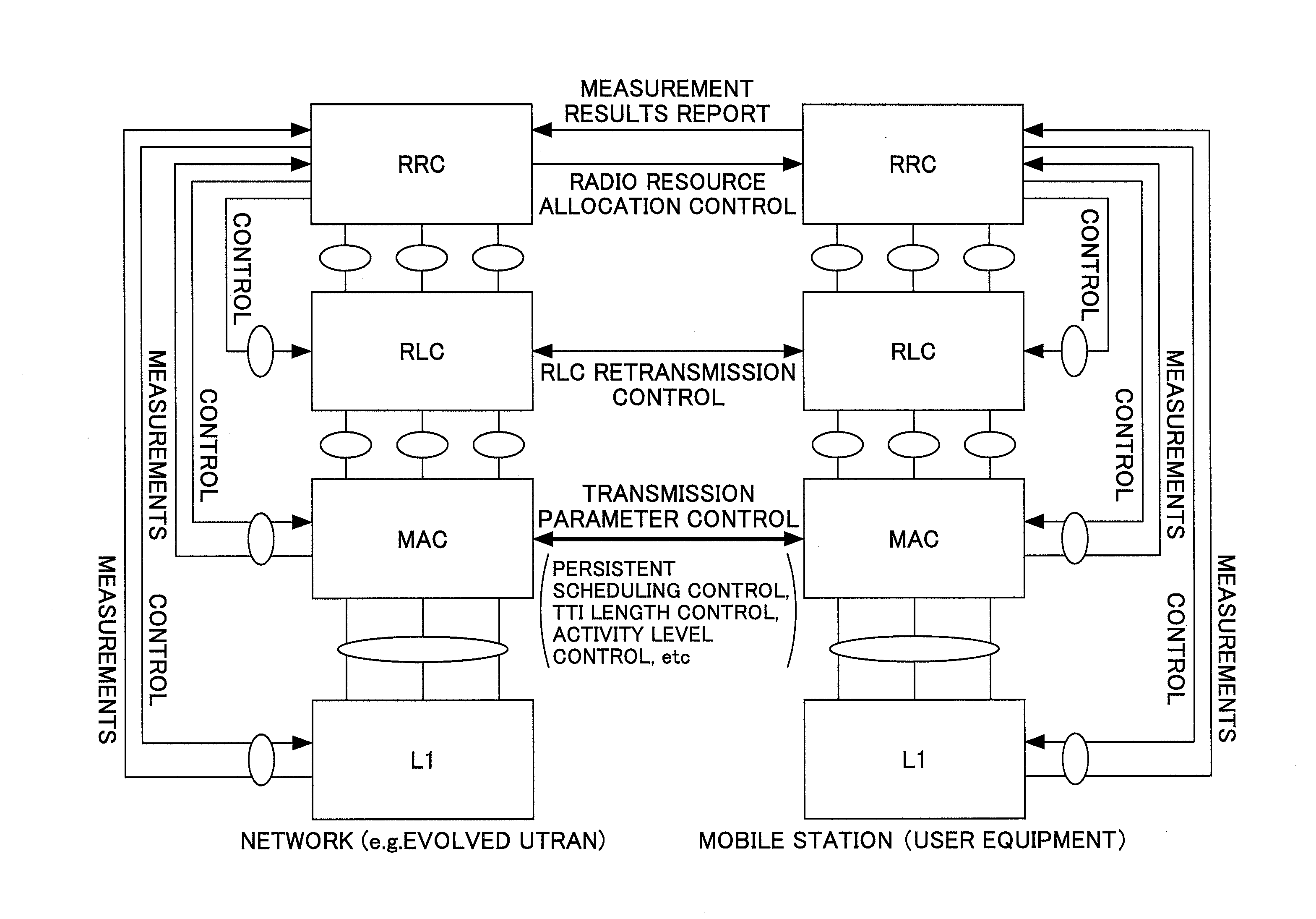
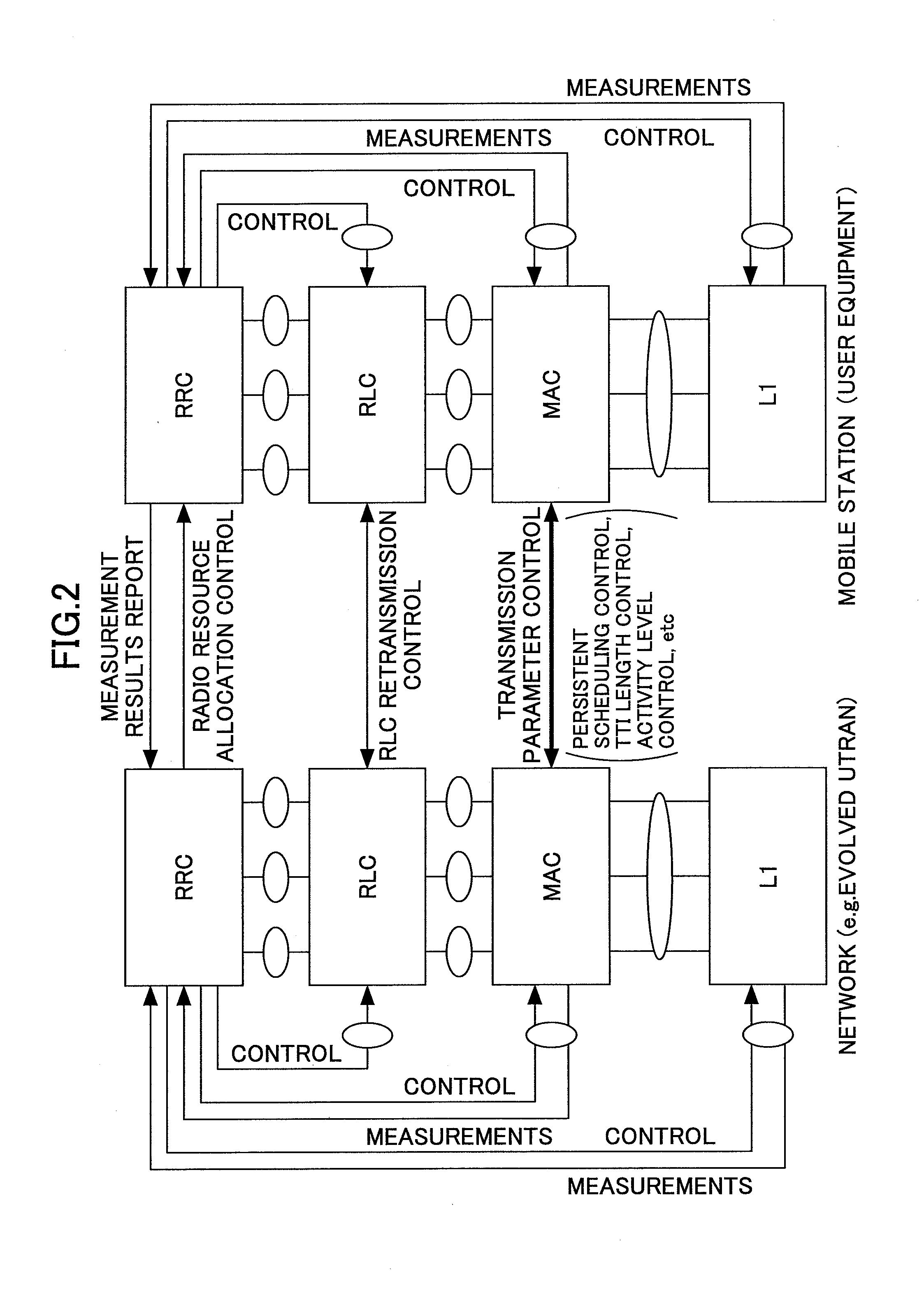
[0050]A description is given below with regard to preferred embodiments of the present invention, with reference to the drawings. FIG. 2 illustrates an example of a control model of an LTE wireless communications system as an example to which the present invention is applied. A Layer 3 RRC (radio resource control) entity sets, maintains, and releases an RRC connection between a mobile ...


PUM


Abstract

A disclosed method of controlling a change of a transmission parameter including the steps of generating a control data unit which does not include a specification of the change timing for changing a parameter value of the transmission parameter for which processing all within a certain layer or sublayer is possible; transmitting the control data unit only in a first half of a transmission frame; and conducting transmission and/or reception, at a timing of a frame following a frame in which the control data unit was transmitted, based on the changed transmission parameter.

Description

BACKGROUND OF THE INVENTION[0001]1. Field of the Invention[0002]The present invention relates generally to a radio communications control technique and specifically to an efficient report timing control for reporting a transmission parameter change.[0003]2. Description of the Related Art[0004]In a third-generation radio access network, a Layer 3 RRC (radio resource control) entity sets and controls radio resources based on a radio parameter (code, frequency, time slot, transport format, mapping, etc.) determined from measurement results reported from a mobile station or a user terminal (UE), as shown in FIG. 1. In a Layer 2 RLC layer, retransmission is controlled using an RLC protocol. A MAC layer performs priority control, scheduling, and mapping of a logical channel to a transport channel to arbitrate between a user and a radio bearer.[0005]When a need arises to change the radio parameter, the change is instructed by upper layer signaling (RRC). In a third-generation communication...

Claims


Application Information

Patent Timeline
Patent Type & Authority Applications(United States)
IPC IPC(8): H04W72/04G06F15/16
CPCH04L1/0007H04L1/0025H04L69/24H04L1/0028H04L1/0027H04L69/322
Inventor HARADA, ATSUSHIISHII, MINAMIABETA, SADAYUKI
Owner NTT DOCOMO INC
Why Eureka
Try Eureka