
Relative Value Notifying Method, Base Station and Mobile Station

a technology of relative value and notification method, applied in the direction of duplex signal operation, signal characterisation, wireless communication, etc., can solve the problems of control delay, value of certain variables differing, and the receiving side apparatus cannot notify the relative value in time, so as to reduce the control delay or the effect of controlling load

Inactive Publication Date: 2008-06-05
NTT DOCOMO INC
View PDF10 Cites 0 Cited by
  • Summary
  • Abstract
  • Description
  • Claims
  • Application Information

AI Technical Summary

Benefits of technology

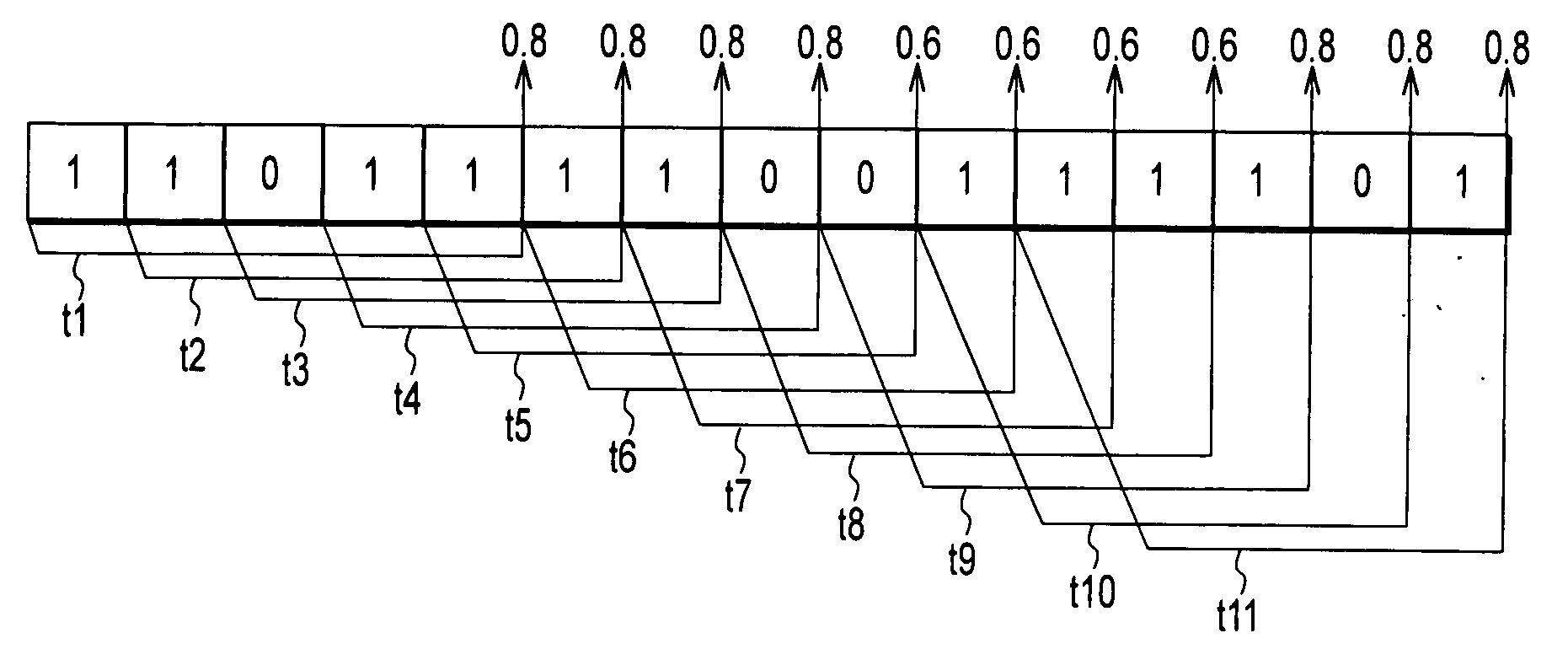
[0014]Accordingly, in view of the above problems, an object of the present invention is to provide a relative value notification method, a base station and a mobile station, which are capable of achieving fairness among receiving side apparatuses while reducing control delay or a control load.

Problems solved by technology

However, in the method, in a case where a transmitting side apparatus transmits individual bits for a long period of time, a receiving side apparatus needs to calculate a relative value by receiving and then decoding all the bits, resulting in a problem of taking time to notify the receiving side apparatus of the relative value.
In other words, the method has problems such as control delay or a load on an apparatus produced by an error correction decoding process.
However, the conventional method for controlling a certain variable according to the “Up” command or the “Down” command has a problem, for example, that the certain variable differs between a receiving side apparatus (a base station or a mobile station) that tracks, from the beginning, a notification channel for notifying the “Up” command or the “Down” command, and a receiving side apparatus that tracks the notification channel from the middle thereof.
In this manner, the method mentioned above has a problem that the value of the certain variable differs depending on a start time of tracking the notification channel.
In other words, there is a problem of difficulty in achieving fairness among receiving side apparatuses.

Method used


Image

  • Relative Value Notifying Method, Base Station and Mobile Station
  • Relative Value Notifying Method, Base Station and Mobile Station
  • Relative Value Notifying Method, Base Station and Mobile Station

Examples


Embodiment Construction

(Configuration of a Mobile Communication System According to an Embodiment of the Present Invention)

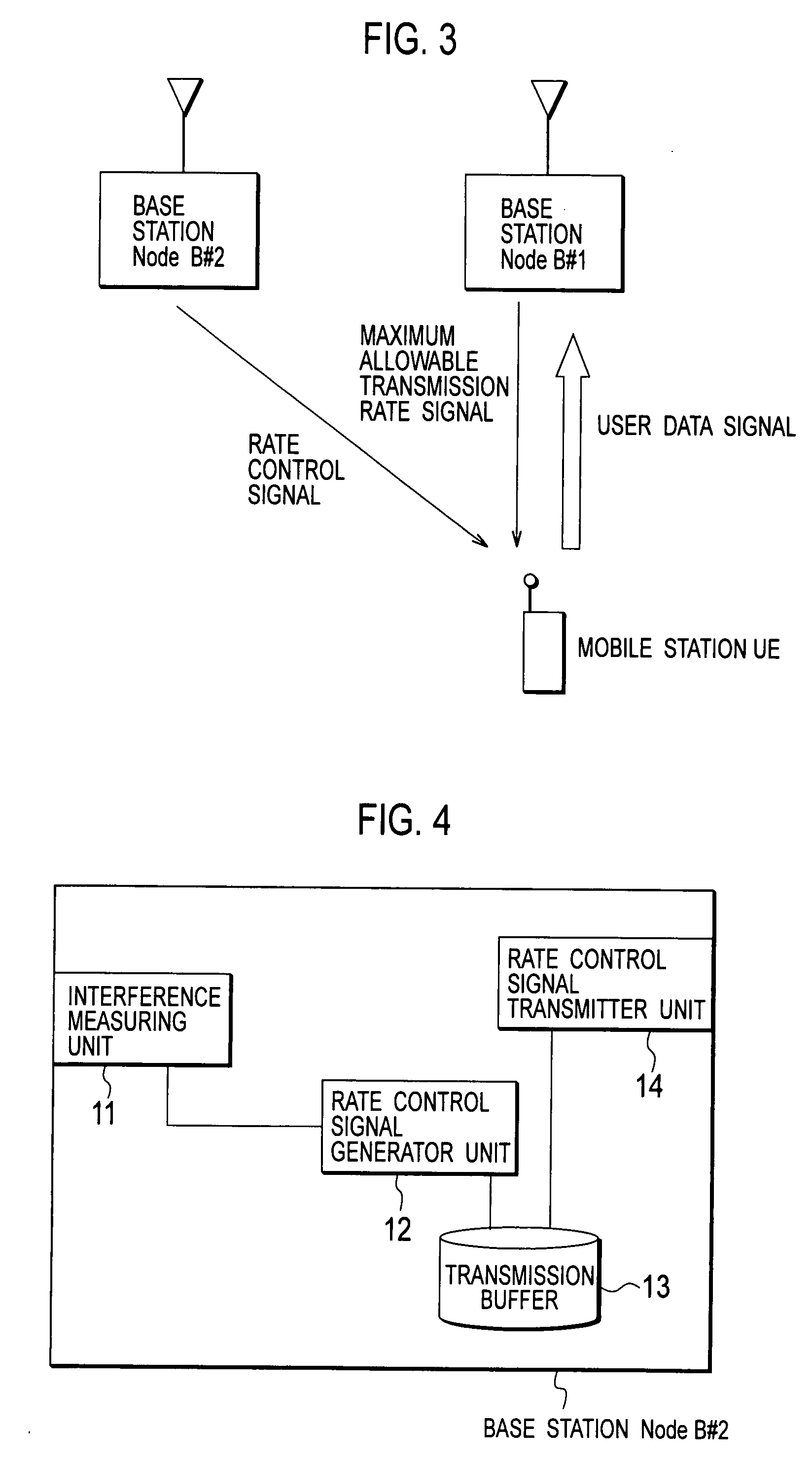
[0029]With reference to FIG. 3 to FIG. 6, description will be given of a configuration of a mobile communication system according to an embodiment of the present invention. In the mobile communication system according to the present embodiment, a base station Node B#2 (a transmitting side apparatus) is configured to notify the relative value of a maximum allowable transmission rate signal (a certain variable) to a mobile station UE (a receiving side apparatus).

[0030]In the example of FIG. 3, a base station Node B#1 is configured to transmit a maximum allowable transmission rate signal for notifying the mobile station UE of the maximum allowable transmission rate (which includes a parameter for calculating the maximum allowable transmission rate, and hereinafter the same shall apply) of an up signal (a user data signal) to be transmitted by the mobile station UE.

[0031]The base station ...


PUM


Abstract

A relative value notification method for notifying a relative value of a certain variable, from a transmitting side apparatus to a receiving side apparatus, includes the steps of: generating, at the transmitting side apparatus, a control signal indicating the relative value by using the number of values 1 or 0 in a plurality of bits to be transmitted during a predetermined period, and transmitting the generated control signal to the receiving side apparatus; and increasing / decreasing, at the receiving side apparatus, the certain variable by using the number of values 1 or 0 in the plurality of bits in the control signal received during the predetermined period.

Description

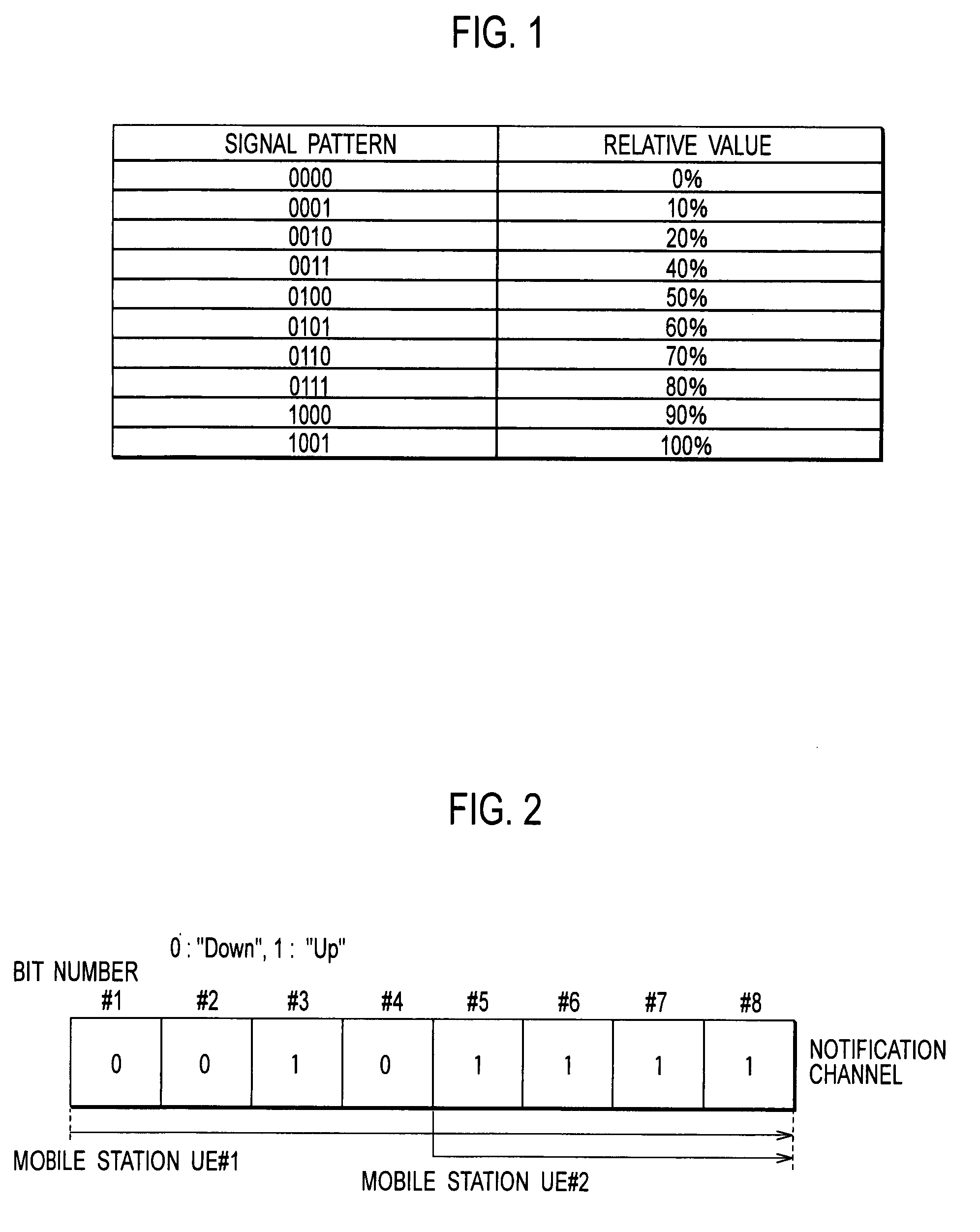
TECHNICAL FIELD[0001]The present invention relates to a relative value notification method, a base station and a mobile station for notifying a relative value of a certain variable, from a transmitting side apparatus to a receiving side apparatus.BACKGROUND ART[0002]Conventionally, in the mobile communication system, the binary number system is used in a case where the relative value of a certain variable is notified from a transmitting side apparatus to a receiving side apparatus in the same way as in the case where the certain variable is notified from a transmitting side apparatus to a receiving side apparatus.[0003]With reference to FIG. 1, description will be given of a method for notifying the relative value of a certain variable from a transmitting side apparatus to a receiving side apparatus with use of the binary number system. In the method, used is a table having a signal pattern and a relative value associated with each other as shown in FIG. 1.[0004]In the method, a tra...

Claims


Application Information

Patent Timeline
Patent Type & Authority Applications(United States)
IPC IPC(8): H04B1/38
CPCH04L1/0002H04L1/0025H04W28/18H04L1/0073H04L1/0036H04W24/00H04W68/00
Inventor USUDA, MASAFUMIUMESH, ANILNAKAMURA, TAKEHIRO
Owner NTT DOCOMO INC
Learn More