Fluorescent lamp driving device and liquid crystal display apparatus using the same

a driving device and fluorescent lamp technology, applied in static indicating devices, instruments, inductances, etc., can solve the problems of inability to distinguish between discharged current and heater current, incorrect control of lamp load current, etc., to reduce the space for attaching the transformer, reduce the control load of the backlight device, and reduce the effect of the liquid crystal display apparatus

Inactive Publication Date: 2009-10-01
SONY CORP
View PDF5 Cites 6 Cited by
  • Summary
  • Abstract
  • Description
  • Claims
  • Application Information

AI Technical Summary

Benefits of technology

[0021]If a heater winding is added to the inverter transformer 5, the transformer for the heater may be omitted. The heaters of the fluorescent lamps may be necessary for pre-heating at a point of starting time of the backlight device as shown in the above-mentioned Japanese Patent Application Publications. Accordingly, during a period of tome about 0.5 to 1 second from a point of power-on time, it may be necessary that only power supply for the heaters of the inverter transformer can output. When such a discharge-starting function that is peculiar to HCFL is provided, the driving control circuit 2 may have an increased control load.
[0022]It is desirable to provide fluorescent-lamp-driving device and a liquid crystal display apparatus using the same, which reduces control load of the driving control circuit 2 as compared with the cases of related art, can be downsized and enables the manufacturing costs thereof to be reduced.
[0026]The alternating current power voltage is supplied to the heaters, which are connected with the transformer, of the high electric potential side of the fluorescent lamps. The driving control circuit increases the frequency of the alternating current power supply to a frequency thereof in which voltage of the fluorescent lamps is equal to a discharge start voltage of the fluorescent lamps or less based on the lamp control signal at a period of starting-up time of the fluorescent lamps, thereby limiting output voltage at the secondary side of the transformer below the output voltage thereof at a period of steady operation time of the fluorescent lamps.
[0029]In the embodiment of the fluorescent-lamp-driving device according to the invention, the transformer containing the windings for driving the heater and for maintaining discharge uses so that providing with the transformers for heaters respectively at a high electric potential side and at a low electric potential side other than a transformer for inverter as related art so as to drive these transformers for heaters separately can be avoided. This enables a space for attaching the transformer to be reduced as compared with a case where the heaters are provided respectively and controlled separately. This also enables control load in the driving control circuit to be reduced. Thus, it is possible to downsize the fluorescent-lamp-driving device and reduce its manufacturing costs.
[0032]In the embodiment of the liquid crystal display apparatus according to the invention, there is provided with the backlight device containing the embodiment of the fluorescent-lamp-driving device according to the invention so that it is possible to prevent the fluorescent lamps from being lighted for a period of pre-heating time thereof from a point of starting-up time of the liquid crystal display apparatus to a point of time where a temperature of the fluorescent lamps reaches a pre-heating temperature of the heaters thereof.
[0033]Thus, the backlight device built-in liquid crystal display apparatus that uses the transformer containing the windings for driving the heater and for maintaining discharge is provided so that providing with the transformers for heaters respectively at a high electric potential side and at a low electric potential side other than a transformer for inverter as the liquid crystal display apparatus of related art so as to drive these transformers for heaters separately can be avoided. This enables a space for attaching the transformer to be reduced as compared with a case where the transformers for the heaters are provided respectively and the heaters are controlled separately. This also enables control load in the backlight device to be reduced. Thus, it is possible to downsize the liquid crystal display apparatus, reduce its weight and reduce its manufacturing costs.

Problems solved by technology

Further, if a driving control is performed while a heater winding is added to the inverter transformer 5, a discharged current of a main body of the fluorescent lamp and a heater current are mixed so that it is difficult to distinguish between the discharged current and the heater current, which may cause a lamp load current to be incorrectly controlled.

Method used


Image

  • Fluorescent lamp driving device and liquid crystal display apparatus using the same
  • Fluorescent lamp driving device and liquid crystal display apparatus using the same
  • Fluorescent lamp driving device and liquid crystal display apparatus using the same

Examples


first embodiment

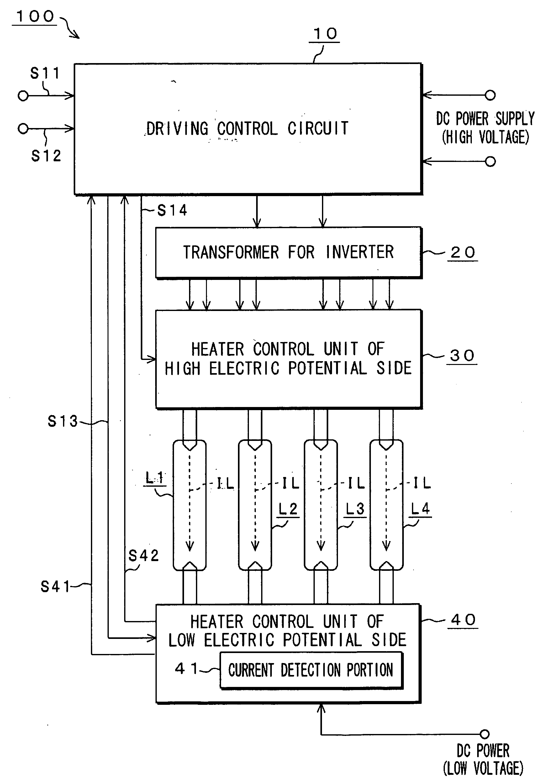
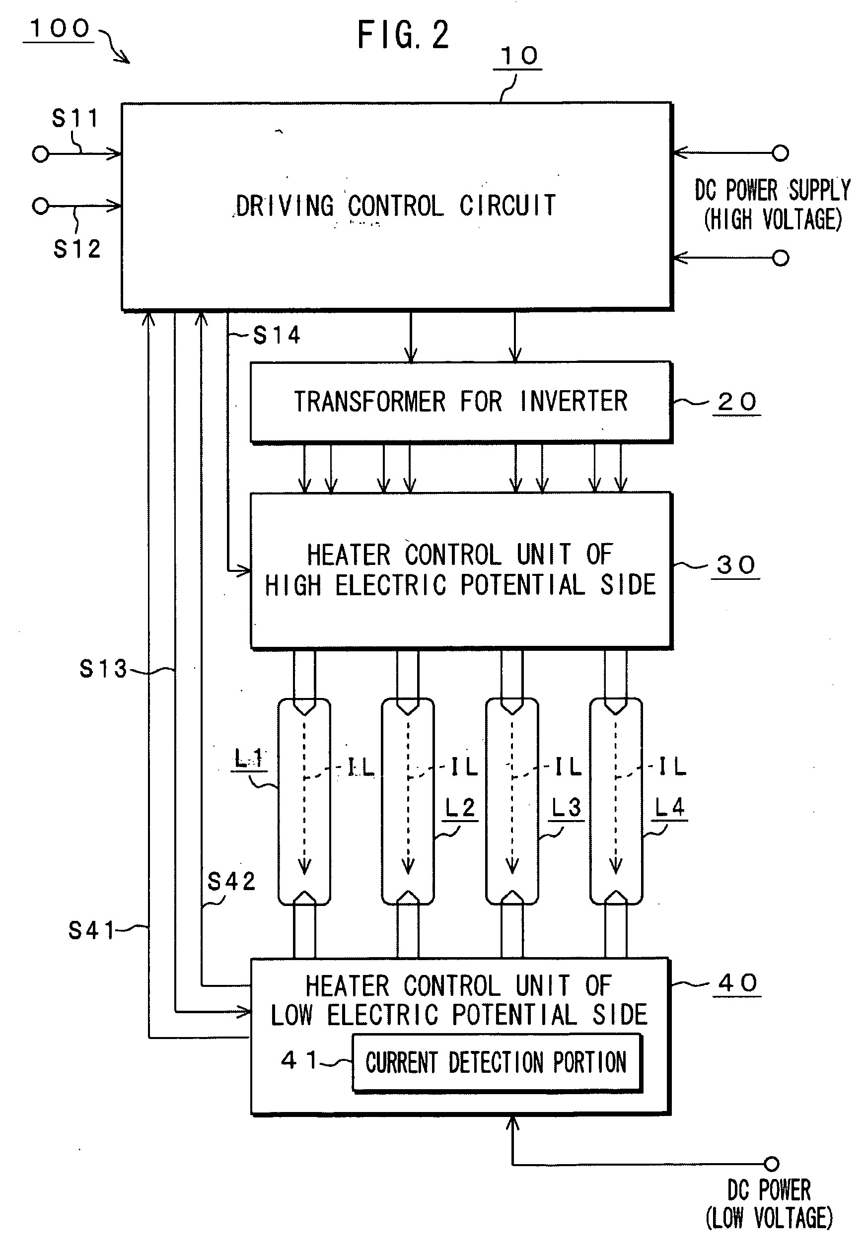
[0044]FIG. 2 shows a configuration of a backlight device 100 according to the invention. FIGS. 3, 4A and 5A show internal configurations of respective components thereof.

[0045]The backlight device 100 shown in FIG. 2 contains an embodiment of a fluorescent-lamp-driving device according to the invention. The backlight device 100 drives a plurality of hot cathode fluorescent lamps (HCFL) so as to be able to adjust their light. The backlight device 100 may be mounted on a liquid crystal display apparatus, for example, a liquid crystal television set of 40 inches. Normally, such a backlight device uses 12 through 20 pieces of fluorescent lamps, but FIG. 2 shows the backlight device 100 in which four pieces of fluorescent lamps L1 to L4 among them are illustrated for its explanation that is easy to understand.

[0046]The backlight device 100, as shown in FIG. 2, contains a driving control circuit 10, a transformer 20 for an inverter, a heater control unit 30 of high electric potential side...

second embodiment

[0104]FIG. 8 shows a configuration of a liquid crystal display apparatus 200 according to the invention. The liquid crystal display apparatus 200 shown in FIG. 8 contains a liquid crystal driver 50, a liquid crystal display unit 60, a power supply unit 70 and an embodiment of the backlight device 100 according to the invention. In the liquid crystal display apparatus 200, light is irradiated to the liquid crystal display unit 60 uniformly.

[0105]The power supply unit 70 connects a commercial power supply of, for example, 100V. The power supply unit 70 mounts a power supply circuit, not shown, for converting the commercial power to two species of direct current voltages of high and low voltages. In this embodiment, the power supply circuit for low voltage converts the commercial power to direct current voltages of 12V by performing full-wave rectification on the commercial power. Similarly, the power supply circuit for high voltage converts the commercial power to direct current volta...


PUM


Abstract

A fluorescent-lamp-driving device contains a driving control circuit that receives direct current power voltage and a lamp control signal for performing drive control on fluorescent lamps and converts the direct current power voltage to alternating current power voltage, and a transformer containing a winding at its primary side and windings for driving a heater and for maintaining discharge at its secondary side. The alternating current power voltage is supplied to heaters of the fluorescent lamps at their high electric potential side. The driving control circuit increases the frequency of the alternating current power supply to a frequency thereof in which voltage of the fluorescent lamps is equal to a discharge start voltage of the fluorescent lamps or less based on the lamp control signal at a period of starting-up time of the fluorescent lamps.

Description

BACKGROUND OF THE INVENTION[0001]1. Field of the Invention[0002]The present invention relates to fluorescent-lamp-driving device that is applicable to a backlight device driving a plurality of hot cathode fluorescent lamps (HCFL), and a liquid crystal display apparatus using the same.[0003]2. Description of Related Art[0004]The backlight device has recently been used in a liquid crystal television or a liquid crystal monitor using a large-scaled liquid crystal display panel. As light source of the backlight device, fluorescent lamps such as a plurality of cold cathode fluorescent lamps (CCFL), a plurality of external electrode fluorescent lamps (EEFL), or LED elements arranged like grid array are often used. As the fluorescent lamps, a plurality of HCFLs each having heaters may have also been used other than CCFL and EEFL.[0005]HCFL has the same structure as that of fluorescent light tube used in a widely distributed lighting apparatus or the like for consumer electrical appliances ...

Claims


Application Information

Patent Timeline
Patent Type & Authority Applications(United States)
IPC IPC(8): H01J61/52H05B41/16
CPCH05B41/295G09G3/3406
Inventor IWAI, KENJI
Owner SONY CORP
Why Eureka
Try Eureka