Storage control sub-system comprising virtual storage units

a storage control and virtual storage technology, applied in memory systems, data processing applications, instruments, etc., can solve the problems of unnecessarily large storage capacity of secondary lu and small data size of data prior to updating that is to be copied

Inactive Publication Date: 2007-03-13
GOOGLE LLC
View PDF12 Cites 38 Cited by
  • Summary
  • Abstract
  • Description
  • Claims
  • Application Information

AI Technical Summary

Benefits of technology

[0012](A) To provide a storage control sub-system whereby, even if an LU pair of large storage capacity is formed in order to create a snap shot, the wasted empty storage region is reduced.
[0013](B) To provide a storage control sub-system whereby the possibility of confusion arising in the host terminal is reduced.

Problems solved by technology

However, in the aforementioned snap shot, the data size of the data prior to update that is to be copied may be small.
Therefore, there may be cases in which the storage capacity of the secondary LU is made unnecessarily large.
Here, if the storage control sub-system reports a different storage capacity to a previously reported storage capacity, with respect to the same LU, then there is a possibility that confusion may result in the host terminal.

Method used


Image

  • Storage control sub-system comprising virtual storage units
  • Storage control sub-system comprising virtual storage units
  • Storage control sub-system comprising virtual storage units

Examples


first embodiment

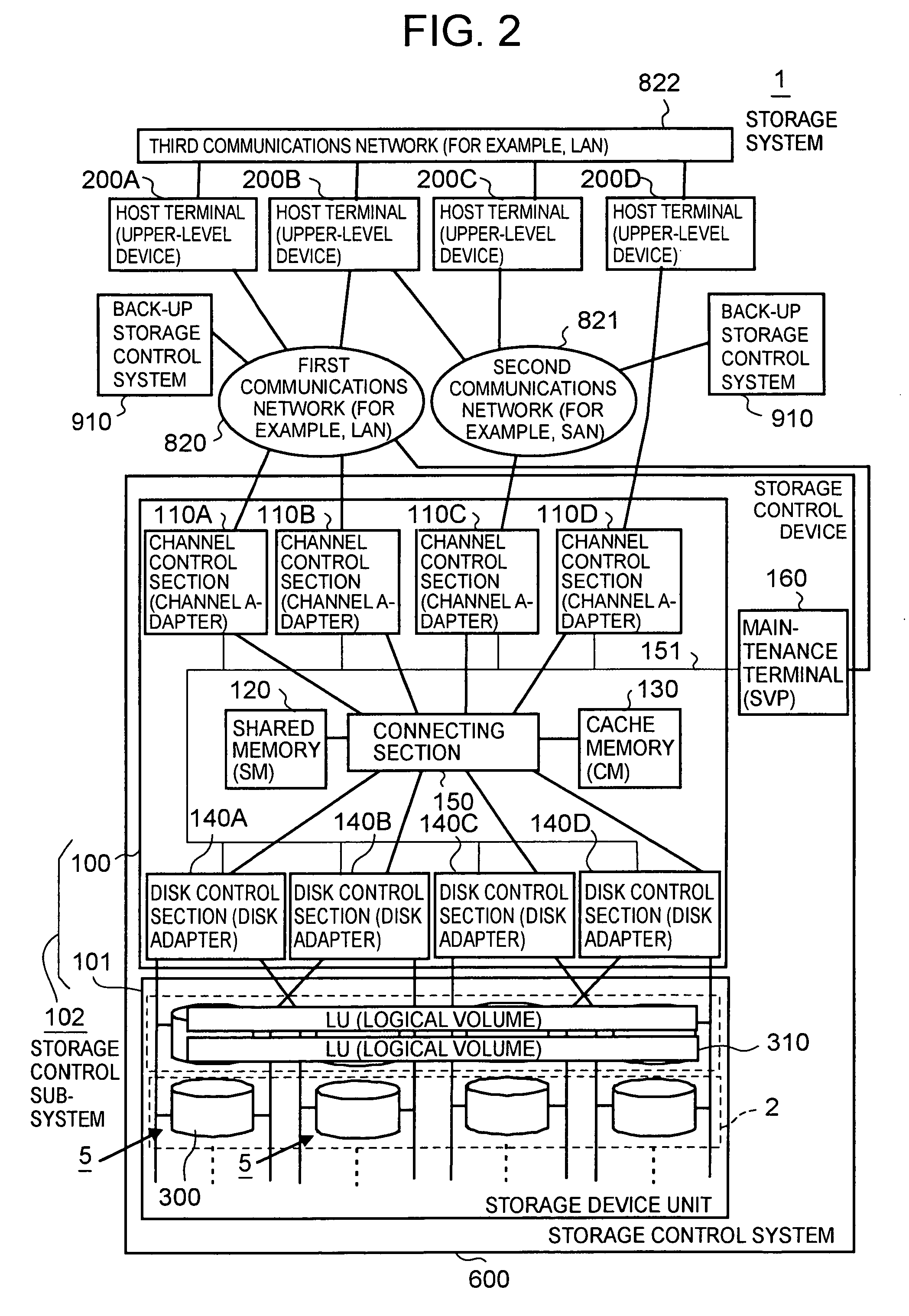
[0160]For example, in a storage control sub-system according to the present invention, if a maintenance terminal for carrying out processing for maintaining the storage control sub-system is connected to the storage control section, then the storage control section receives a unit preparation request for preparing a new virtual storage unit, from the maintenance terminal or an external terminal connected to the maintenance terminal, and in response to this unit preparation request, it provides a graphical user interface containing, at the least, an input box for the virtual storage capacity value, to the maintenance terminal or the external terminal, and it stores the virtual storage capacity value input to this input box, in the memory, as the established virtual storage capacity value.

second embodiment

[0161]For example, in a storage control sub-system according to the present invention, if the storage control sub-system forms unit pairs consisting of two storage units, taking one of the storage units as a primary storage unit and the other storage unit as a secondary storage unit, in such a manner that a snap shot is taken which copies the data in the primary storage unit to the secondary storage unit, then a plurality of logical storage devices are provided in the physical storage device, this plurality of logical storage devices comprises two or more first logical storage devices having a logical storage region which can be associated with a virtual storage region, and one or more second logical storage devices having a logical storage region which cannot be associated with a virtual storage region, the one or more second logical storage devices constituting a single real storage unit connected to the host terminal, and the storage control section forming a unit pair, wherein t...

fifth embodiment

[0164]In a storage control sub-system according to the present invention, for example, if the storage control section has received a read capacity command from the host terminal, then it reports the virtual storage capacity value stored in the memory to the host terminal.


PUM


Abstract

A storage control device provided in a storage control sub-system reports a virtual storage capacity value stored in a shared memory, to a host terminal, and ensures that, after the virtual storage capacity value has been stored in the host terminal, the virtual storage capacity value thus reported cannot be changed while the virtual storage unit having the virtual storage capacity value is connected to the host terminal.

Description

CROSS-REFERENCE TO PRIOR APPLICATION[0001]This application relates to and claims priority from Japanese Patent Application No. 2004-31150, filed on Feb. 6, 2004, the entire disclosure of which is incorporated herein by reference.BACKGROUND OF THE INVENTION[0002]1. Field of the Invention[0003]The present invention relates to a storage control sub-system comprising virtual storage units.[0004]2. Description of the Related Art[0005]For example, in a storage system for trunk business use, which handles a large volume of data, a storage control sub-system constructed separately from the host computers (below, referred to as “host terminals”) is used to manage data. This storage control sub-system comprises, for example, a RAID (Redundant Array of Independent Inexpensive Disks) constituted by providing a plurality of disk type storage devices in an array fashion.[0006]For example, Japanese Patent Laid-open-No. (Hei) 9-288547 discloses a system wherein a plurality of physical devices align...

Claims


Application Information

Patent Timeline
Patent Type & Authority Patents(United States)
IPC IPC(8): G06F17/30G06F13/10G06F3/00G06F3/06G06F12/00G06F15/16
CPCG06F3/0608G06F3/0614G06F3/0632G06F3/0689G06F3/0664Y10S707/99943G06F2213/0038
Inventor WATANABE, HARUAKIURABE, KIICHIROYAMAGAMI, KENJI
Owner GOOGLE LLC
Why Eureka
Try Eureka