Two-stage attachment for cutting, crimping etc, and mechanical method thereof

a two-stage attachment and crimping technology, applied in the field of tools, can solve the problems of many tools designed for a particular task that are limited to one specific function, many tools designed for a particular task do not provide any versatility, and many tools sacrifice the qualities inherent in single-purpose tools

Active Publication Date: 2007-03-20
BRAILOVSKIY ALEKSANDR M
View PDF26 Cites 20 Cited by
  • Summary
  • Abstract
  • Description
  • Claims
  • Application Information

AI Technical Summary

Problems solved by technology

Many tools in this field are limited to one specific function.
In addition, most tools designed for a particular task do not provide any versatility, even for that particular task.
Many tools have been designed to provide additional versatility, but many of those tools have sacrificed some of the qualities inherent in single-purpose tools.
Two tools were required because well-known bolt cutters with straight edge jaws perform very poorly on cables.
However, the tool requires highly specialized hardware for sharpening the blades and it is critical to maintain the sharpness of the blades for cutting cable.
Blades have a tendency to wear out with use.
If the cutting edges wear out or dull even slightly and are used to cut cable, they tend to shear through a portion of the cable's thickness and then “chew” on the cable between the blades.
Furthermore, the tool uses blades configured to shear that are enclosed inside one another, which requires the tool to have a width exceeding that of squeezing or crushing type cutters and limits to the tool's usefulness.
U.S. Pat. No. 5,862,597 to Juros (see FIGS. 2A–2C), discloses a tool that makes it possible to bring the cutting action as close to a point of applied force as physically allowable, but doing so comes at a cost.
Considering structural properties of the materials involved, the width of the tool must exceed that of most conventional cutters, thus restricting its use in narrow openings, such as between pipe flange faces.
For all practical purposes the increased angle nullifies the benefit of the handles being shorter, and makes them unsafe and uncomfortable to use.
Additionally, the tool does not provide for inexpensive and easily replaceable blades.
Nevertheless, eventually one still has to replace blades that cost nearly as much as an entire new tool.
The issue of replaceable blades was addressed by EP0011545 to Muller (see FIG. 4A) and U.S. Pat. No. 5,898,998 to Deville (see FIG. 4B), but the solution suggested therein, while being suitable for use in many tool designs, is not entirely satisfactory.
First, the design weakens the blade support.
The design also does not facilitate a uniform transfer and distribution of tension within the metal structures of the blade and blade support, which accelerates fatigue of the structures.
In exchange, this improvement renders the cutter practically incapable of cutting anything thinner than the distance between the jaws when they are opened to about two-thirds of their capacity.
But such attachments come at relatively high cost, and, except for JP 02002078988, it is doubtful that they are easily demountable.

Method used


Image

  • Two-stage attachment for cutting, crimping etc, and mechanical method thereof
  • Two-stage attachment for cutting, crimping etc, and mechanical method thereof
  • Two-stage attachment for cutting, crimping etc, and mechanical method thereof

Examples


Embodiment Construction

[0038]Reference will now be made in detail to the preferred embodiments of the present invention, examples of which are illustrated in the accompanying drawings.

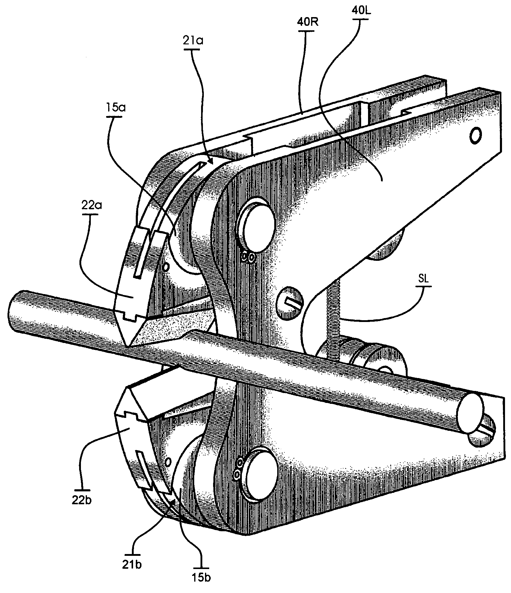
[0039]The present invention, in a broad sense, is a two-stage lever arrangement designed to provide a compact device with an improved mechanical advantage to apply a cutting, shearing, squeezing and / or piercing force. The device can be configured for manual or powered operation.

[0040]A segmented eccentrically pivoted cam, as opposed to fully circular or elliptical cam, is used as a part of a lever of a first stage. A working surface of the cam imparts a force to a working surface of another pivoted member, or a blade support, which thus effectively becomes a lever of a second stage. The present invention arranges for two-stage lever action to occur within the same spatial dimensions as those allowing for merely one-stage lever action in conventional tools.

[0041]Means for linking each cam lever to the respective blade support...


PUM

PropertyMeasurementUnit
angleaaaaaaaaaa
angleaaaaaaaaaa
lengthaaaaaaaaaa

Abstract

A two-stage attachment includes two stages of levers arranged to apply a cutting, shearing, squeezing and / or piercing force. The first stage includes a cam lever that has a segmented arcuate pushing surface. The second stage includes a blades support that has an arcuate yielding surface. The pushing surface contacts the yielding surface such that force applied to the cam lever is transmitted to the blade support through the contact between the surfaces.

Description

CROSS-REFERENCE TO RELATED APPLICATIONS[0001]This application claims priority to U.S. Provisional Patent Application No. 60 / 510,166, filed on Oct. 8, 2003, entitled TWO-STAGE ATTACHMENT FOR CUTTING, CRIMPING ETC, AND MECHANICAL METHOD THEREOF, which is incorporated herein by reference in its entirety.BACKGROUND OF THE INVENTION[0002]This invention is related to tools and, more particularly, to tools for performing operations requiring an application of a severing or squeezing force, such as cutting or crimping metal rods, bolts and cables.[0003]Many tools in this field are limited to one specific function. Thus, a user must acquire and maintain a large amount of hardware in the course of doing business. In addition, most tools designed for a particular task do not provide any versatility, even for that particular task.[0004]Many tools have been designed to provide additional versatility, but many of those tools have sacrificed some of the qualities inherent in single-purpose tools. ...

Claims


Application Information

Patent Timeline
Patent Type & Authority Patents(United States)
IPC IPC(8): B26B17/02B25B7/12B25B27/10
CPCB25B7/126B25B27/10B26B17/02B23D17/02B23D29/023B23D29/002H01R43/042B26F1/36B23D29/00
Inventor BRAILOVSKIY, ALEKSANDR M.
Owner BRAILOVSKIY ALEKSANDR M
Why Eureka
Try Eureka