Head-down enhanced vision system

Active Publication Date: 2007-03-27
ROCKWELL COLLINS INC
View PDF7 Cites 73 Cited by
  • Summary
  • Abstract
  • Description
  • Claims
  • Application Information

AI Technical Summary

Benefits of technology

[0010]An advantage of the invention is that enhanced vision system functionality may be provided in aircraft that are not able to install or use a complete HUD system.
[0011]The invention provides an enhanced vision system for an aircraft including an imaging sensor mounted on the aircraft. The imaging sensor detects a range of radiation emanating from a scene. A display-generating processor is operationally connected to the sensor and generates, from inputs relating to aircraft operation, symbology representing information useful to operation of the aircraft. The display-generating processor combines the generated symbology with the detected range of radiation from the imaging sensor to create a representation of the scene. The representation of the scene is created such that the generated symbology is scaled to conformally overlay the detected range of radiation. A display is operationally connected to the processor. The display is configured to display the representation of the scene such that the representation of the scene is non-conformal with a pilot's view out of a windshield of the aircraft.
[0012]The invention also provides an enhanced vision system for an aircraft, including means for detecting a range of radiation emanating from a scene.

Problems solved by technology

Unfortunately, there are some situations where it is not feasible to install or use a complete HUD system.
For example, some airplane cockpits may not have enough spac

Method used


Image

  • Head-down enhanced vision system
  • Head-down enhanced vision system
  • Head-down enhanced vision system

Examples


Example

DETAILED DESCRIPTION OF THE DRAWINGS

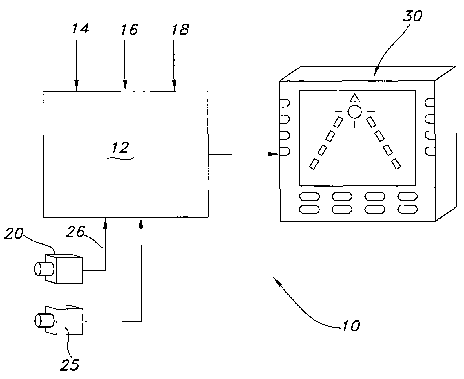
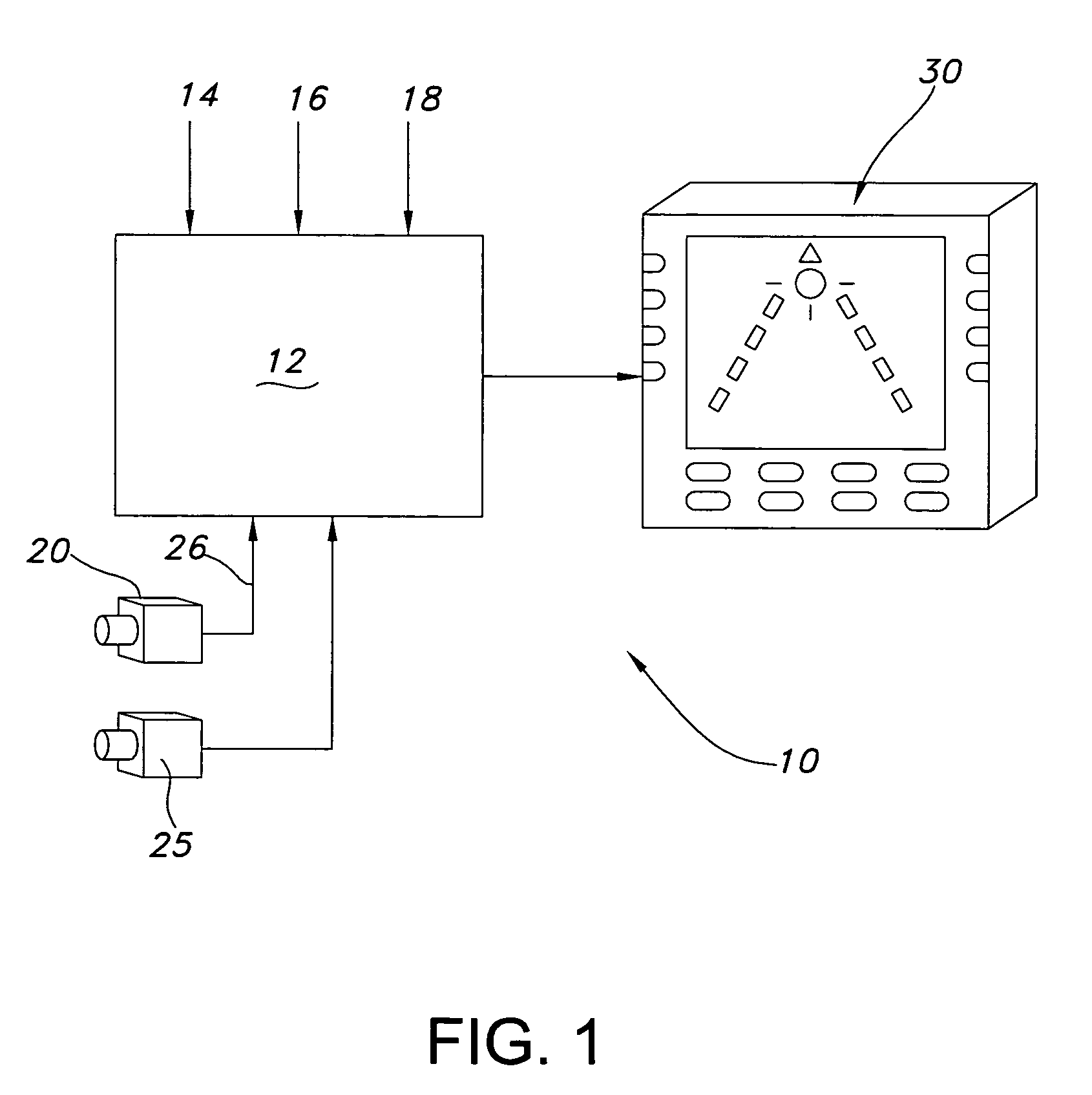
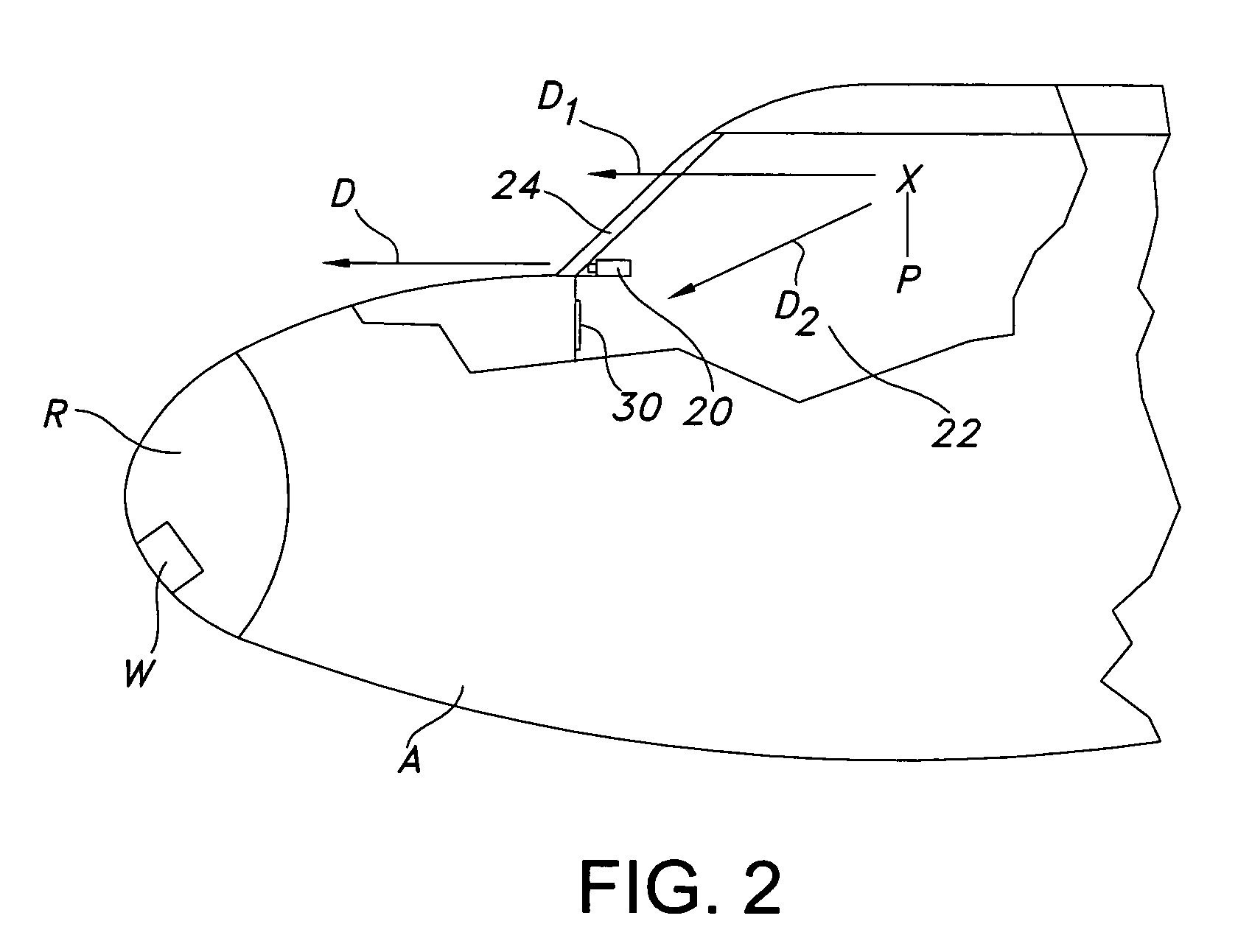
[0018]FIGS. 1 and 2 depict an enhanced vision system 10 (EVS) according to an embodiment of the invention. System 10 includes a processor 12, one or more sensors 20 operationally connected to the processor, and a display 30 operationally connected to the processor and located nonconformally with a pilot's view of a scene. Processor accepts inputs 14, 16, 18 from other aircraft systems (not shown). Inputs 14, 16, 18 may include information relating to the operating conditions of the aircraft A, such as airspeed, attitude, altitude, bearing, flight path vector, and the like. Inputs 14, 16, 18 also may include information relating to environmental conditions, such as air temperature, ground temperature, and the like. The inputs may also provide guidance information, such as instructions to the pilot to use a certain runway or taxiway. Processor 12 uses inputs 14, 16, 18 to generate symbology that represents information useful to operation of the airc...


PUM


Abstract

An enhanced vision system for an aircraft is disclosed. The system includes an imaging sensor mounted on the aircraft. The imaging sensor detects a range of radiation emanating from a scene. A display-generating processor is operationally connected to the imaging sensor and generates symbology representing information useful to operation of the aircraft. The display-generating processor combines the generated symbology with the detected range of radiation from the imaging to create a representation of the scene. The representation of the scene is created such that the generated symbology is scaled to conformally overlay the detected range of radiation. A display is operationally connected to the processor. The display is configured to display the representation of the scene such that the representation of the scene is non-conformal with a pilot's view out of a windshield of the aircraft.

Description

FIELD OF THE INVENTION[0001]The invention relates to the aircraft navigation, and more particularly, to the visual display of aircraft flight information for observation by a pilot.BACKGROUND OF THE INVENTION[0002]Head-up display (HUD) systems are currently used in aircraft to provide pilots with essential information superimposed onto their forward field of view through the aircraft windshield. The information displayed by the HUD typically includes data in a symbolic format indicative of flight conditions, such as the operating conditions of the aircraft (e.g., attitude, airspeed, and altitude), or guidance information. HUD systems are also being designed for use in automobiles and other vehicles.[0003]A typical HUD system includes a viewing element, called a combiner, that is placed in a pilot's forward field of view. The combiner is substantially transparent but is treated to be reflective to certain wavelengths of light. When symbolic information is projected onto the combiner ...

Claims


Application Information

Patent Timeline
IPC IPC(8): G02F1/01
CPCG01C7/00
Inventor WOOD, ROBERT B.DESMOND, JOHN P.WILSON, JOHN G.
Owner ROCKWELL COLLINS INC
Why Eureka
Try Eureka