[0009]In view of the foregoing, it is an object and
advantage of the present invention to provide an apparatus for growing plants in a plurality of vertically spaced containers which provides even distribution of fluid, such as water either with or without dissolved or undissolved plant nutrients, to each growing compartment of the uppermost plant growing container. The present invention provides a structure which operates such that fluid not absorbed within an upper planting compartment is positively delivered only to a single
lower compartment, assuring that if fluid is evenly applied at the uppermost compartments, it is evenly distributed to each lower plant growing compartment in the stack. A further aspect of the invention assures delivery of fluids to the outer regions of each plant growing compartment in a manner such that the even delivery of fluid is not reliant upon the wicking properties of the plant growing media. According to a further aspect of the invention, visual
verification of even delivery of fluids to each plant growing compartment is provided. The invention allows for readily quantitatively measuring actual fluid delivery to any
single plant growing container in the stack if desired. According to a further aspect of the invention, distribution of fluids is carried out by way of base plate which, in addition to aiding uniform and visually verifiable distribution of fluid, also provides protection of the upper edges of each plant growing container against
UV degradation and mechanical damage. In the present invention, the fluid path down through the stack is preferably located away from the central support pole so that fluid will not tend to bypass the
growth medium in the container by flowing along any bypass fluid path which might exist between the support pole and the
growth medium in the container. The present invention prevents plants from being deprived of adequate fluid as can occur in prior art devices as a result of the opening of such a bypass fluid path. The invention also can be readily adapted into various shapes and sizes of components which may be retrofitted to improve existing installations of prior art vertical planting systems. Certain embodiments of the present invention provide positive separation of the roots of different plants within a container.
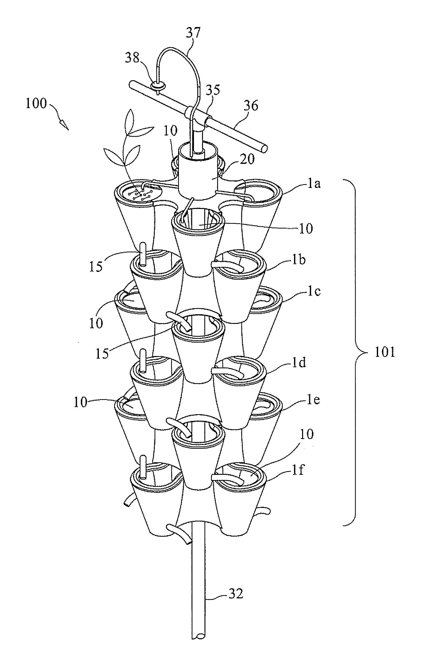
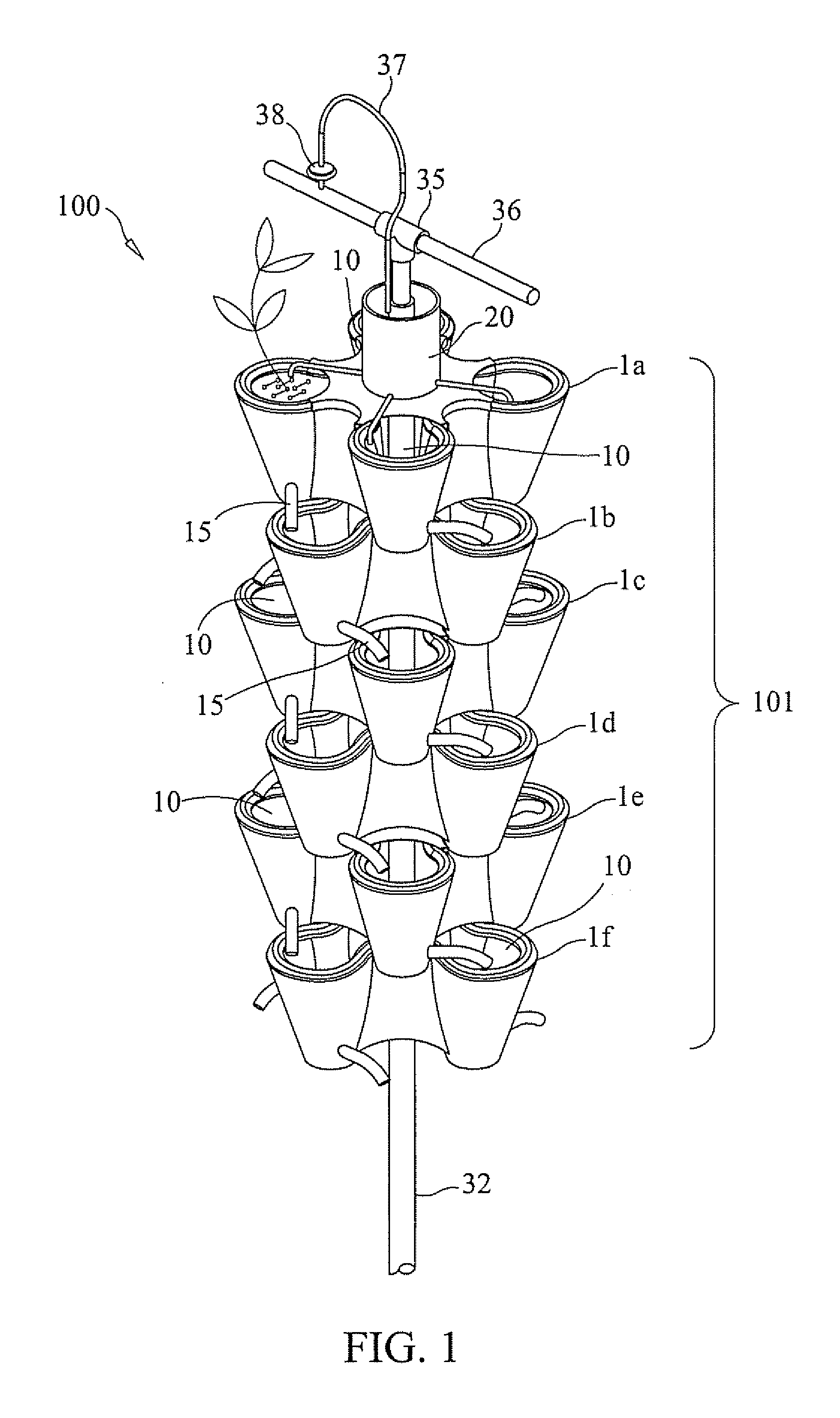
[0010]A preferred embodiment of the present invention includes a plant growing container with or partially-partitioned plant growing compartments, each compartment fitted with a directionally adjustable or non-adjustable fluid
drain tube located at the bottom of each compartment which directs fluid (water and / or plant nutrients) into a
single compartment of the next lower container. Each tube provides means for directing fluid flow outward and away from the central area of the next lower container to the desired area of the receiving compartment. Tubes are preferably transparent, but are not required to be, to enhance visual verification of fluid delivery to the intended receiving compartment. Fluid flow from each compartment of the lowest container in the stack provides redundant visual verification that fluid has been positively delivered to every plant growing compartment in the stack. Directionally adjustable or non-adjustable drain tubes may be retrofitted to prior art containers.
[0011]
Three dimensional surface features are preferably molded onto the bottoms of the plant growing containers to mate with the container walls, partitions, or other features of the next lower container in the stack to assure desired axial and
rotational alignment of the containers.
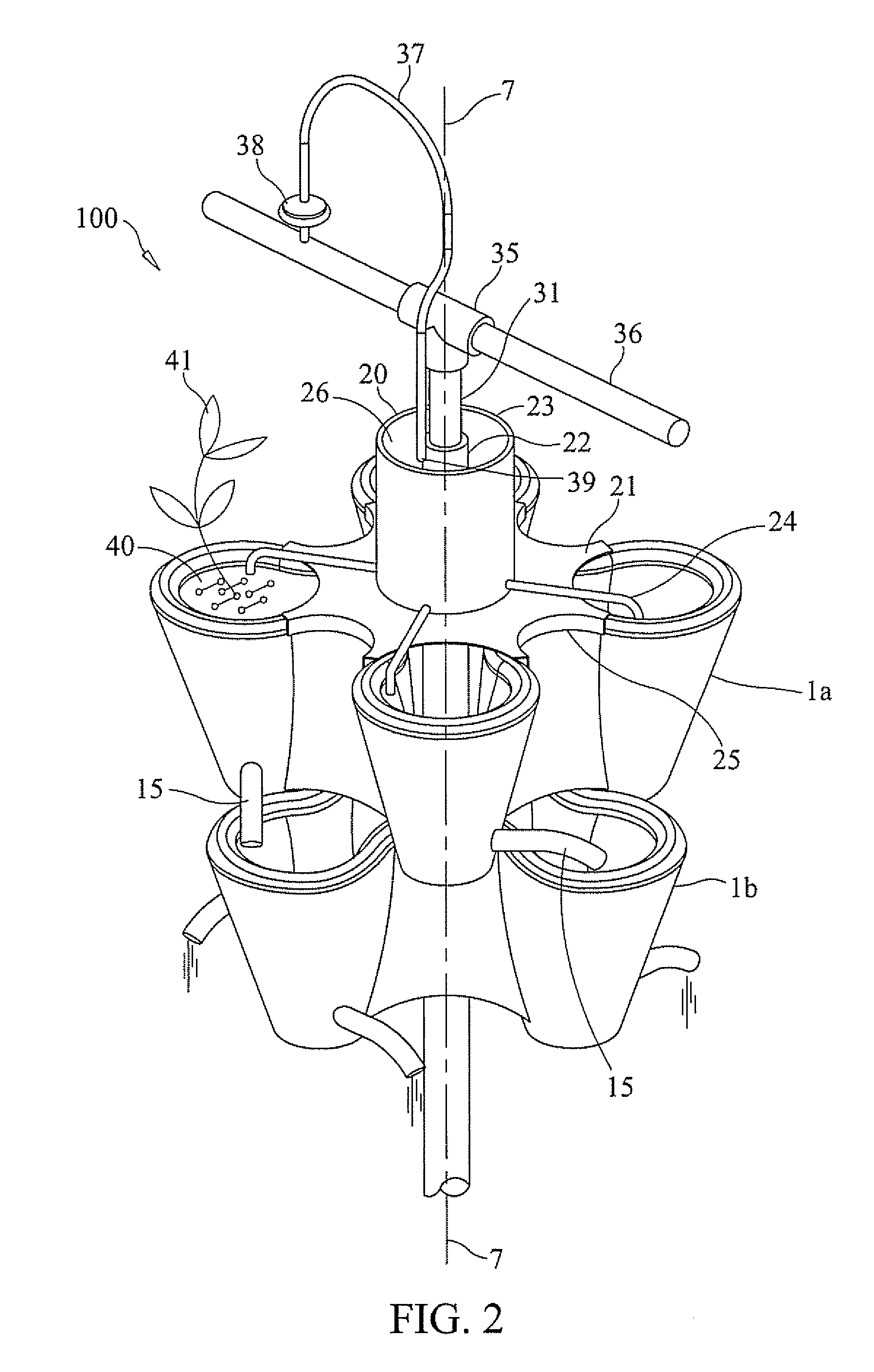
[0012]Preferred embodiments of the present invention include a fluid
distribution system for low pressure delivery and distribution of fluid to each of the plant growing compartments of the uppermost plant growing container in the stack. This fluid
distribution system may comprise a base plate which fits atop the uppermost plant growing container. The base plate is shaped to
overlay the central area of the container and to
overlay a portion of or all of the upper
peripheral edges of the plant growing compartment walls. Features on the underside of the base plate are designed to engage the compartment walls, partitions, or other features of the plant growing container on which it rests. The base plate has a through-hole on its central axis. Passing concentrically through this through-hole is a
cylindrical tube sealed at its intersection with the base plate. The inside
diameter of this tube provides clearance for a stack support pole to pass through. Mounted atop the base plate, concentric with the
cylindrical tube is a larger
diameter tube, sealed at its base. The volume between the two concentric cylinders comprises a fluid reservoir atop the base plate. Located near the bottom of the outer
cylindrical tube and passing through its wall are drain tubes, one tube discharging into each of the plant growing compartments of the plant growing container on which the base plate rests. The top area of the reservoir may be open or it may be topped by a cover rotationally fixed to the support pole but not to the reservoir. A
fluid supply tube connected to an overhead
fluid supply mainline discharges fluid into the reservoir, through the cap, if one is present. The
fluid supply tube may include a fluid flow
regulator. The fluid drain tubes, fluid supply line, and fluid flow
regulator are sized such that fluid is delivered to the reservoir at a faster rate that it is being discharged through the reservoir drain tubes.
[0013]Embodiments of the present invention preferably include a support pole which passes axially through the stacked growing containers and the fluid
distribution system. In addition to serving as an axial support for the stacked plant growing containers and support for the fluid distribution
system, it also acts as a support for an overhead fluid supply mainline. The support pole is driven into the earth to a depth which establishes the desired elevation of the fluid delivery mainline. A support tube, larger in inside
diameter than the support pole is placed onto the support pole and is driven into the earth to a depth which establishes the desired elevation of the stacked plant growing containers. A thrust
washer is placed onto the support pole and rests upon the upper end of the support tube. The growing containers, when stacked onto the support pole, are vertically supported by this thrust
washer. The stack of plant growing containers and the fluid distribution
system atop the uppermost container all may be freely rotated as a unit about the support pole.
[0014]A second preferred embodiment of the plant growing container of the present invention includes fully-partitioned or partially-partitioned plant growing compartments with each compartment provided with fluid drain holes at the bottom of each compartment. The partitions are rotationally oriented to assure that fluid drains into a
single compartment of the next lower container. The partitions may be molded as an integral part of the container or may comprise a fitted insert that provides equivalent compartment partitioning and sealing. Fluid flow from each compartment of the lowest container in the stack of containers provides visual verification of fluid flow to every plant growing compartment in the stack.

