
Secondary lithium ion battery containing a prelithiated anode

a lithium ion battery and prelithiated anode technology, applied in the field of secondary batteries, can solve the problems of fragments no longer active in providing electrons to the external circuit, fragments that are easily pulverized or fragmented, and high dilated particles or thin films are extremely brittle and prone to pulverization or fragmentation, so as to prolong the charge-discharge cycle and improve the specific capacity.

Active Publication Date: 2012-08-14
GLOBAL GRAPHENE GRP INC
View PDF28 Cites 117 Cited by
  • Summary
  • Abstract
  • Description
  • Claims
  • Application Information

AI Technical Summary

Benefits of technology

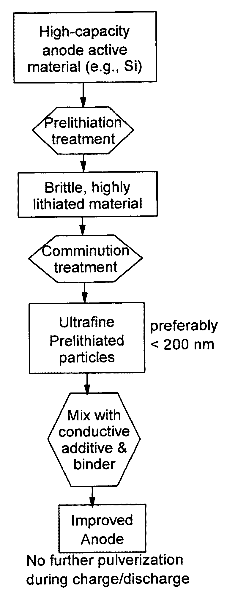
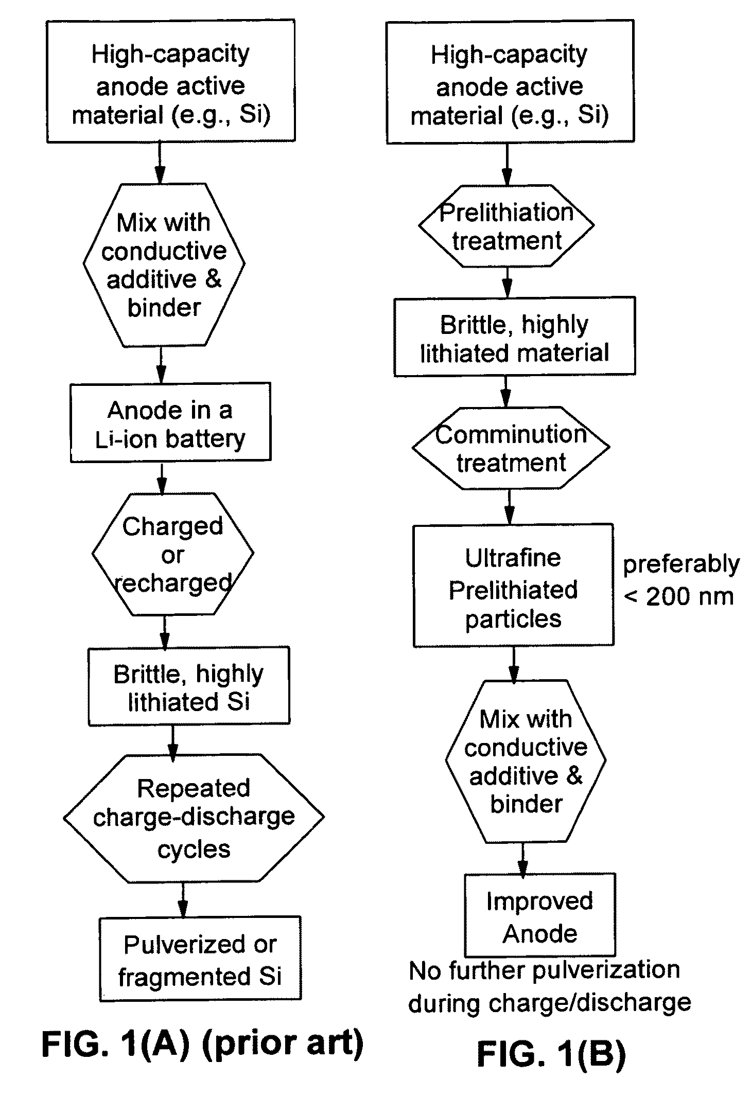
[0068](a) We have surprisingly found that prelithiated materials can be much more readily converted into nano-scaled particles as compared to their non-lithiated counterparts. It is well known in the art that the preparation of nano materials has been usually slow and expensive. Prelithiation makes such a process much faster and less expensive. Nano particles also mean a shorter distance for lithium ions to penetrate in and out of the particles, resulting in a better rate capacity for the battery. In other words, the electrode can quickly store or release lithium and, hence, the battery can be discharged or re-charged rapidly. This is a highly beneficial feature for a battery that is intended for electric vehicle applications, where a fast discharge rate capability (e.g., during acceleration) is required. In all battery applications, a fast re-charge rate is clearly a highly desirable feature. A driver can quickly recharge a car battery in a matter of 10 to 60 minutes instead of several hours.

Problems solved by technology

Such highly dilated particles or thin film are extremely brittle and prone to pulverization or fragmentation.
During repeated charge / discharge cycles, the anode active material tends to quickly become pulverized and the resulting fragments lose contacts with the conductive additive and the current collector.
Those fragments are no longer active in providing electrons to the external circuit.
It is well known in the art that the preparation of nano materials has been usually slow and expensive.
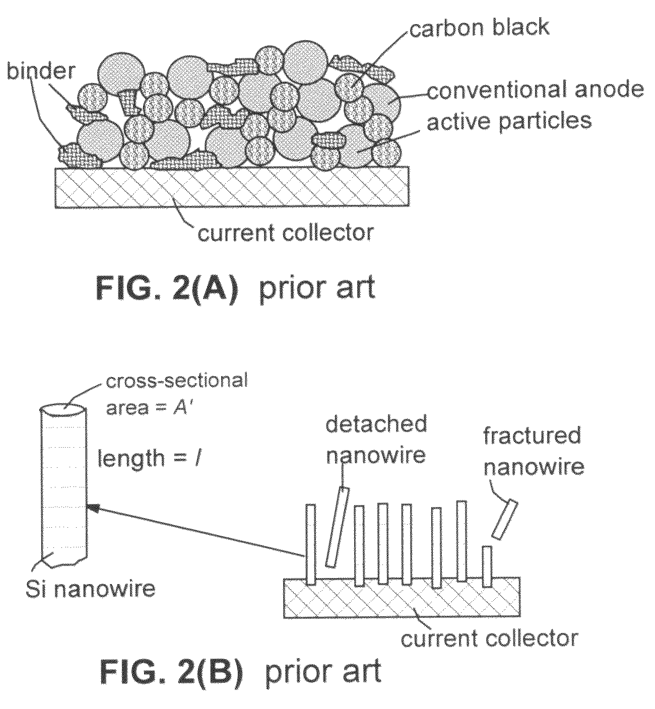
There are severe drawbacks associated with these prior art end-connected nanowire-based electrodes.
Furthermore, if fragmentation of a nanowire occurs, only the segment remaining in direct contact with the current collector (e.g., steel plate in Chan, et al.) could remain in electronic connection with the current collector and all other segments will become ineffective since the electrons generated will not be utilized.
Additionally, the configuration of having parallel nanowires perpendicular to a current collector is not compatible with the current battery production practice, which typically involves high-speed winding and packaging of multiple layers of electrodes and separator.

Method used


Image

  • Secondary lithium ion battery containing a prelithiated anode
  • Secondary lithium ion battery containing a prelithiated anode
  • Secondary lithium ion battery containing a prelithiated anode

Examples


example 1

[0126]Summarized in FIG. 3 are the results of a study that illustrates the impressive advantages of the presently invented anode technology. The sample was prepared by using the prelithiated Si particles coated with amorphous carbon (13% after carbonization of phenolic resin) and bonded by PVDF as the working electrode and lightly lithium-plated Cu foil as the counter electrode and reference electrode. A specific discharge capacity as high as 2,500 mAh per gram of (Si+C) was maintained after 20 cycles. By contrast, non-prelithiated Si particles, with or without a carbon coating, exhibit a high initial capacity, but the capacity rapidly fades away as the number of repeated charge / discharge cycles increases.

example 2

[0127]FIG. 4 shows the results of ball-milling prelithiated and non-prelithiated Si particles. Clearly, prelithiated particles can be more easily reduced to sub-micron scales. This is a highly surprising, yet desirable result considering the fact that, in general, nano particles have been difficult and expensive to produce. The present invention unexpectedly discovers an efficient way to cost-effectively produce nano particles.

example 3

[0128]We have also investigated the cycling behaviors of several samples, including Si—NGP—C nanocomposite, Si—C nanocomposite (no NGP), and graphite-filled C—Si nanocomposite solid particle-based anodes (all containing Si nano particles). One of the samples prepared contains approximately 15% NGPs, 60% Si nano particles, and 25% carbon matrix and is herein designated as Sample-A. The corresponding sample containing Si nano particles that are prelithiated is designated Sample-A-P. For comparison purpose, a Comparative Sample-B was prepared by dispersing Si nano particles (approximately 70%) in a pitch matrix, as in Sample-A, but without the presence of any NGP. A corresponding sample containing Si nano particles that are prelithiated is denoted as Sample-B-P. A Comparative Sample-C was prepared by replacing NGPs with fine natural graphite particles (average diameter=3.5 μm) obtained by air-jet milling of natural flake graphite. A corresponding sample containing Si nano particles tha...


PUM

PropertyMeasurementUnit
sizeaaaaaaaaaa
particle sizeaaaaaaaaaa

Abstract

A lithium ion battery that exhibits a significantly improved specific capacity and much longer charge-discharge cycle life. The battery comprises an anode active material that has been prelithiated and pre-pulverized. This anode may be prepared with a method that comprises (a) providing an anode active material; (b) intercalating or absorbing a desired amount of lithium into the anode active material to produce a prelithiated anode active material; (c) comminuting the prelithiated anode active material into fine particles with an average size less than 10 μm (preferably <1 μm and most preferably <200 nm); and (d) combining multiple fine particles of the prelithiated anode active material with a conductive additive and / or a binder material to form the anode. Preferably, the prelithiated particles are protected by a lithium ion-conducting matrix or coating material. Further preferably, the matrix material is reinforced with nano graphene platelets.

Description

FIELD OF THE INVENTION[0001]The present invention provides a secondary battery, particularly a rechargeable lithium-ion battery that comprises an anode containing a prelithiated anode active material.BACKGROUND[0002]The following list of references is closely related to the prior art. These references will be cited from time to time in the specification. They will be indicated as [Ref. xx] or simply [xx], where xx denotes a numeral.List of References[0003]1. J. Zhang, et al., “Carbon Electrode Materials for Lithium Battery Cells and Method of Making Same,” U.S. Pat. No. 5,635,151 (Jun. 3, 1997).[0004]2. Q. Liu, et al., “Composite Carbon Materials for Lithium Ion Batteries, and Method of Producing Same,” U.S. Pat. No. 5,908,715 (Jun. 1, 1999).[0005]3. J. K. Jacobs, et al, “Negative electrode for a rechargeable lithium battery comprising a solid solution of titanium dioxide and tin dioxide,” U.S. Pat. No. 6,007,945 (Dec. 28, 1999).[0006]4. D. G. Fauteux, et al., “Electrode materials h...

Claims


Application Information

Patent Timeline
Patent Type & Authority Patents(United States)
IPC IPC(8): H01M4/02H01M4/38H01M4/36
CPCH01M4/134H01M4/364H01M4/366H01M4/38H01M4/587H01M4/625H01M4/626H01M10/0525H01M2004/021Y02E60/122Y02T10/7011Y02E60/10
Inventor ZHAMU, ARUNAJANG, BOR Z.
Owner GLOBAL GRAPHENE GRP INC
Learn More