Movable control panel for a patient support

a control panel and patient technology, applied in the direction of machine supports, sofas, gearing, etc., can solve the problems of poor ergonomic position, difficult to see the control switch on the input surface, and difficult use of controllers

Inactive Publication Date: 2007-04-10
HILL ROM SERVICES
View PDF160 Cites 51 Cited by
  • Summary
  • Abstract
  • Description
  • Claims
  • Application Information

AI Technical Summary

Problems solved by technology

This is a very poor ergonomic position.
The severe angle between the patient and the controller makes the control switches on the input surface very difficult to see.
Also, such controllers are very difficult to use since the patient must either reach across his or her body to access a controller built into one siderail, or bend his or her arm and wrist in an awkward angle to access a controller built into the other siderail.
While pendant controllers may be handheld, avoiding some of the ergonomic problems of built in controllers, pendant controllers may be stolen, lost, misplaced, dropped to the floor or otherwise rendered difficult or impossible to access by a patient in the bed.
Moreover, pendant controllers may be damaged when dropped.
Indeed, tethered pendant controllers are further disadvantageous in that they present a choking hazard.
Moreover, tethered pendant controllers are relatively difficult to clean, thereby presenting other health hazards.

Method used


Image

  • Movable control panel for a patient support
  • Movable control panel for a patient support
  • Movable control panel for a patient support

Examples


Embodiment Construction

[0016]While the present device is susceptible to various modifications and alternative forms, exemplary embodiments thereof have been shown by way of example in the drawings and will herein be described in detail. It should be understood, however, that there is no intent to limit the device to the particular forms disclosed, but on the contrary, the intention is to address all modifications, equivalents, and alternatives falling within the spirit and scope of this disclosure as defined by the appended claims.

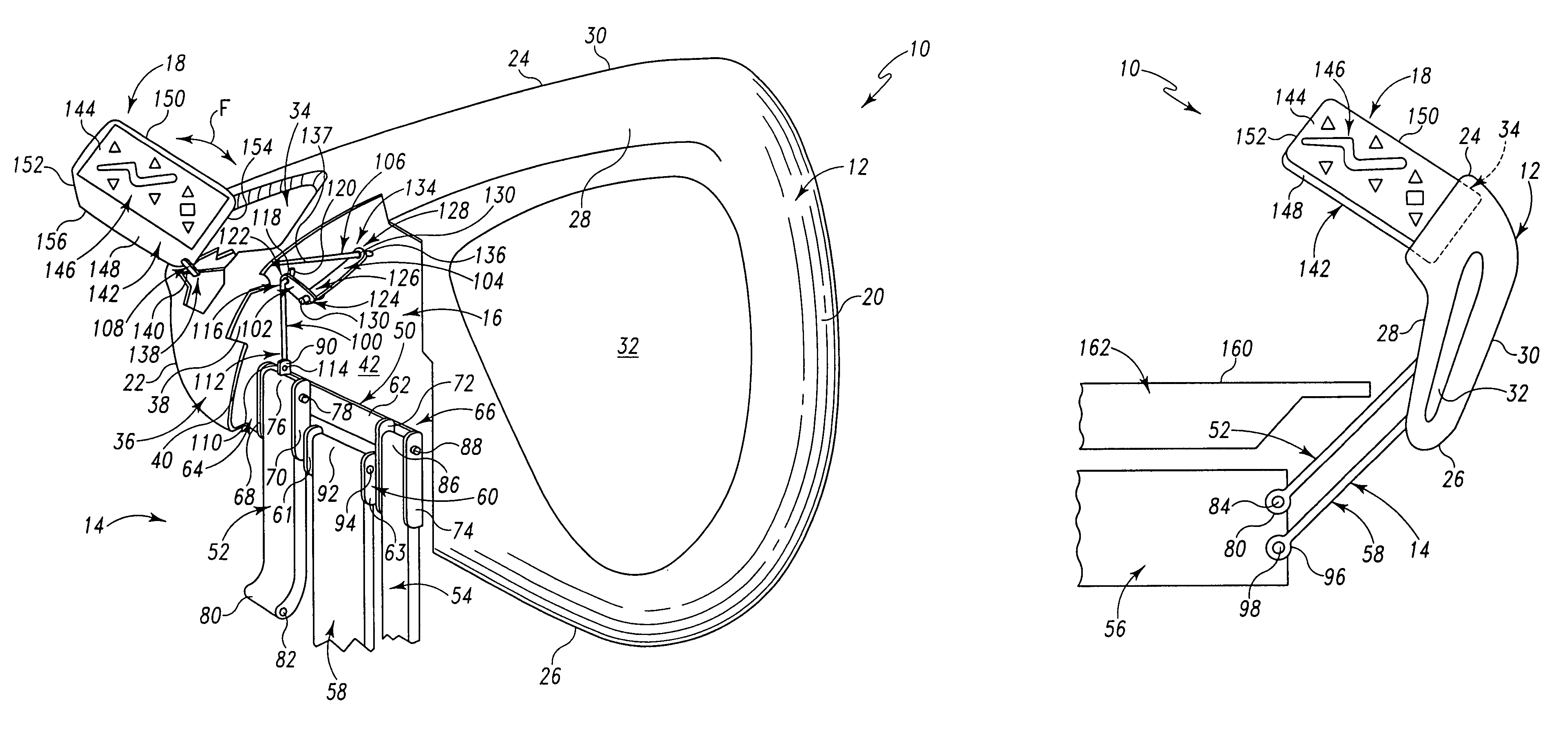
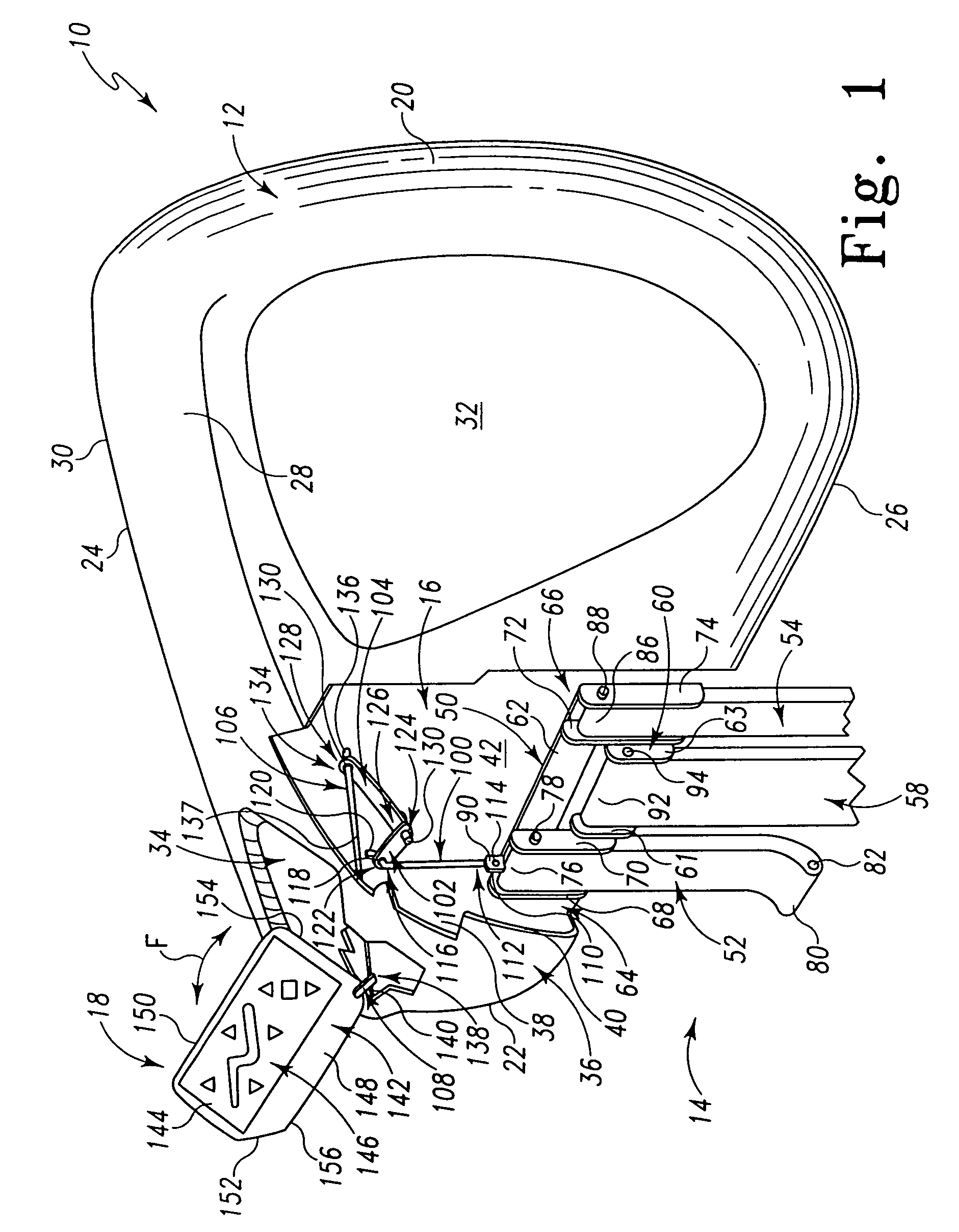
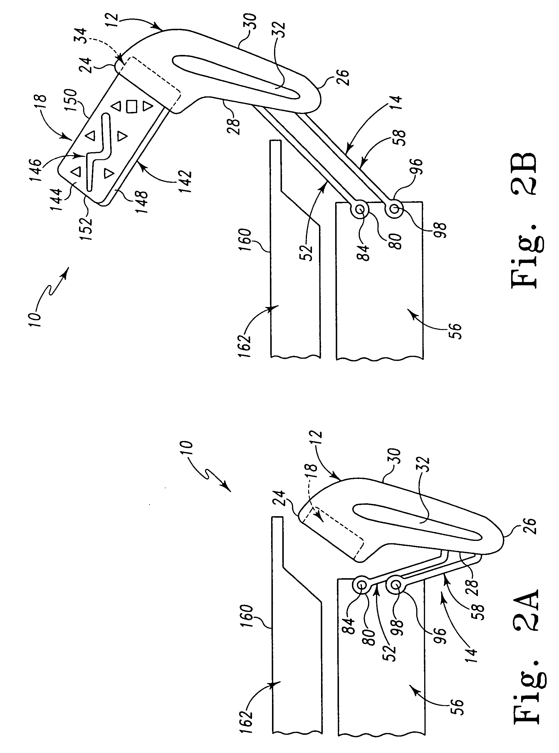
[0017]Referring now to FIG. 1, an embodiment of a control panel of the present invention, generally referred to by the numeral 10, includes a controller 18 coupled to a support structure of a patient support (not shown) by a linkage mechanism 16. In one application, the support structure is a siderail 12, which in turn is coupled to a hospital bed (not shown) by a linkage assembly 14. The siderail is generally coupled to the head end of the bed, so as to be adjacent to the patie...


PUM


Abstract

A movable control panel for a patient support is provided. The patient support includes a support structure which is movable between a raised position and a lowered position relative to a patient support. A controller is coupled to the support structure for movement between a deployed position and a stored position. A mechanism for coupling the controller to the support structure is also provided. The controller includes control switches that are operable to adjust a position of the patient support. The coupling mechanism is operable to move the controller between the deployed position and the stored position in response to movement of the support structure between the raised position and the lowered position, respectively.

Description

RELATED APPLICATIONS[0001]This application claims the benefit of U.S. Provisional Patent Application Ser. No. 60 / 538,341, filed Jan. 22, 2004, which is incorporated herein by this reference.FIELD OF THE INVENTION[0002]The present device generally relates to a control for a patient support (such as a hospital bed), and more particularly to a controller connected to the patient support such that movement of a support structure of the patient support (for example, a siderail) between a raised position and a lowered position relative to the patient support causes movement of the controller between a deployed position and a stored position, respectively.BACKGROUND AND SUMMARY[0003]It is known to provide a controller for a patient support, such as a hospital bed, to enable a user to perform a variety of functions including adjusting the bed configuration by, for example, raising or lowering the bed, tilting the bed, or raising, lowering, and / or tilting a portion of the bed relative to ano...

Claims


Application Information

Patent Timeline
Patent Type & Authority Patents(United States)
IPC IPC(8): A47C21/08A61G7/00A61G7/015A61G7/018A61G7/05F16H35/14F16M11/00F16M13/02
CPCA61G7/0507A61G7/018A61G2203/726A61G2007/0524A61G2007/0509A61G7/0509A61G7/0524
Inventor HEIMBROCK, RICHARD H.
Owner HILL ROM SERVICES
Why Eureka
Try Eureka