Clamp coupling for pipes

a technology of clamping and pipes, applied in the direction of snapping fasteners, buckles, transportation and packaging, etc., can solve the problem that clamping couplings cannot be used in narrow spaces with difficult access, and achieve the effect of reliable coupling securing

Inactive Publication Date: 2007-05-01
PUTZMEISTER CONCRETE PUMPS GMBH
View PDF19 Cites 26 Cited by
  • Summary
  • Abstract
  • Description
  • Claims
  • Application Information

AI Technical Summary

Problems solved by technology

Such clamp couplings can often not be employed in difficult to access locations in narrow spaces due to the need to pivot the clamp lever about greater than 90° axially parallel to the circular opening.

Method used


Image

  • Clamp coupling for pipes
  • Clamp coupling for pipes
  • Clamp coupling for pipes

Examples


Embodiment Construction

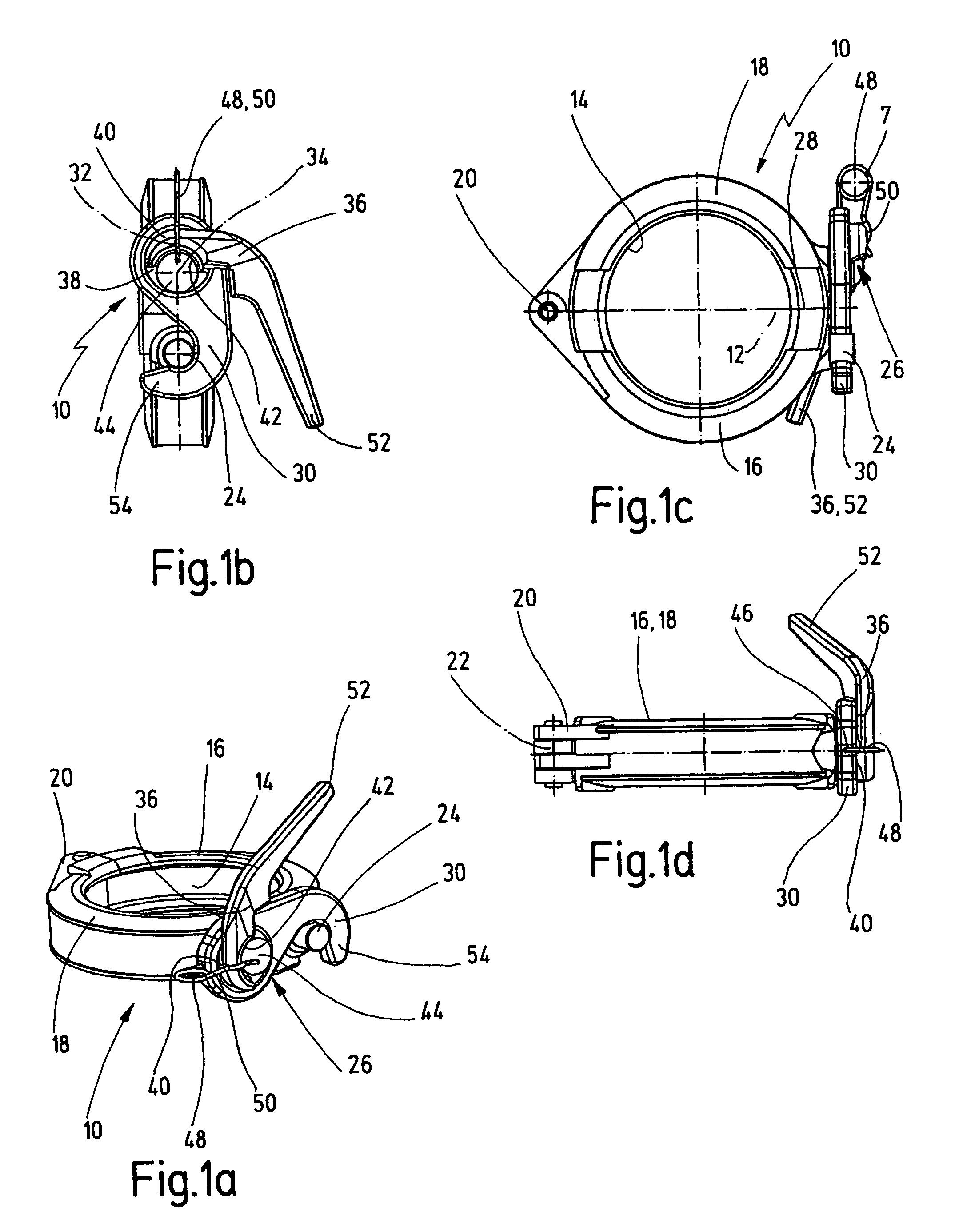
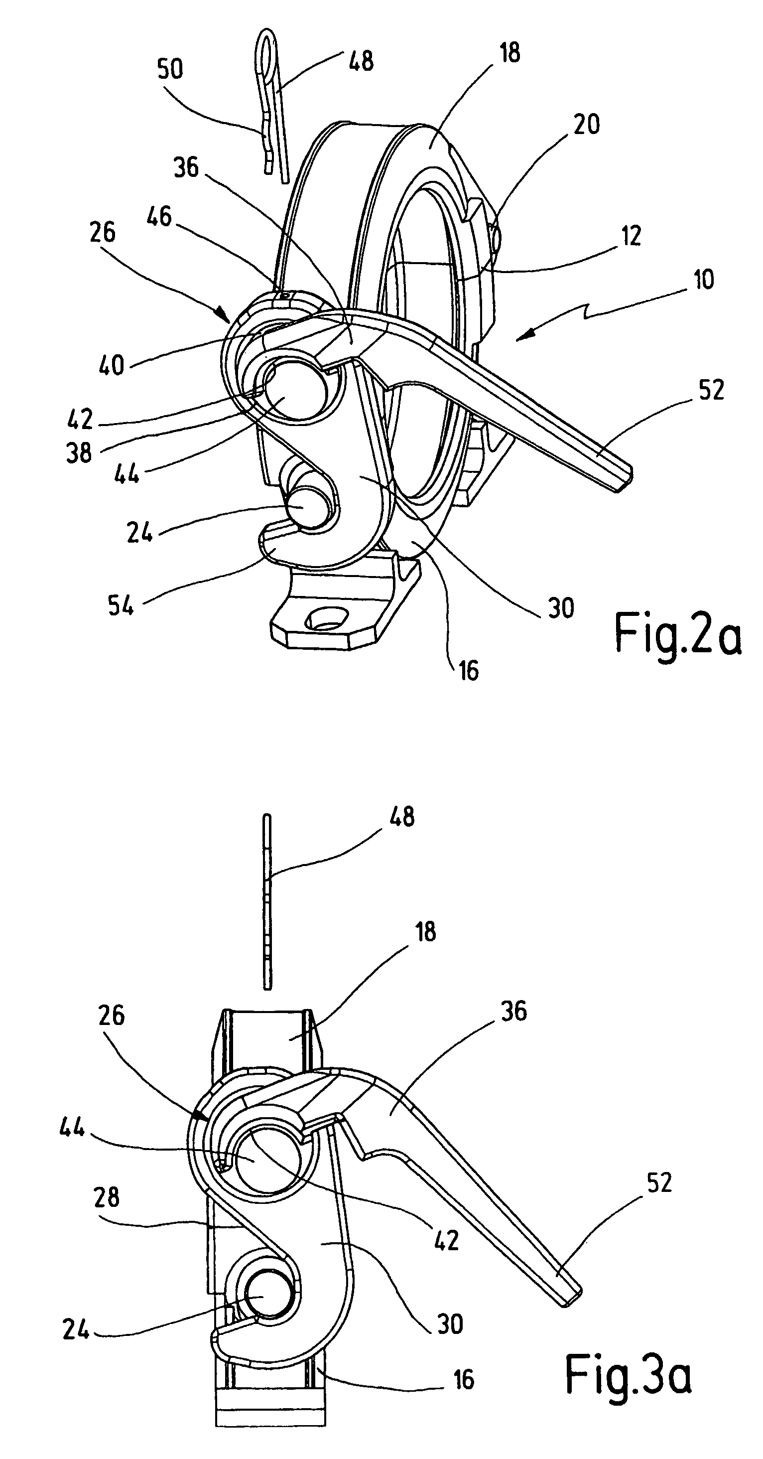
[0020]The clamp coupling shown in the figures is designed for connecting pipe segments. It is used for example for connecting two not shown pipe segments of a pressure conveyance conduit for thick matter and is employed there above all in difficult to access locations due to the limited space available. The clamp coupling 10 includes two clamp shells 16, 18 arranged essentially mirror symmetrically to a separating plane 12, in which in the coupling position shown in FIG. 1c they form a round opening 14 for defining the passage through of a pipe. The coupling shells 16, 18 are pivotable relative to each other about an axis 22 parallel to the circular opening 14 via an externally located linkage 20 lying in the separating plane 12 at their one end. On its end opposite to the linkage 20 the first clamp shell 16 exhibits a radially outwardly projecting latch pin 24 in the form of a cylindrical dowel and the second clamp shell 18 exhibits a locking mechanism 26 which cooperates with the ...


PUM


Abstract

The invention concerns a clamp coupling for coupling pairs of pipes. Such clamp couplings are used, for example, for coupling concrete conduits from concrete pumps. This clamp coupling (10) comprises two clamp shells (16, 18) which, in the coupling state, define a circular opening (14) for the passage-through of the pipes. The coupling shells can be pivoted relative to each other via a pivot linkage (20) at their one end, and have a locking mechanism (26) provided at their other end. In order to be able to fasten the clamp coupling (10) even in confined spaces, the locking mechanism (26) comprises a locking hook (30) which, in the closed state, positively grasps a latch pin (24) provided on the other coupling clamp (16), and pulls the clamp shells (16, 18) towards each other at their point of separation (28) opposite the linkage (20). During the opening process, the locking hook (30) can be lifted from the latch pin (24) and pivoted out of its engaged position about a pivoting axis (32) which is perpendicular to the linkage axis (22). The locking mechanism (26) also comprises a clamping lever (36) which can be pivoted relative to the coupling clamp about a lever axis (34) which is perpendicular to the linkage axis. The clamping lever is also operatively associated with the locking hook (30).

Description

CROSS REFERENCE TO RELATED APPLICATION [0001]This application is a national stage of PCT / EP01 / 13154 filed Nov. 14, 2001 and based upon DE 100 57 304.5 filed Nov. 17, 2000 under the International Convention.BACKGROUND OF THE INVENTION[0002]1. Field of the Invention[0003]The invention concerns a clamp coupling for the pair-wise coupling of pipes, the pipes having substantially radially projecting coupling flanges at the ends facing each other, the clamp coupling comprising two clamp shells which, in the coupled state, define a circular opening for the passage-through of the pipes, said shells pivotable relative to each other about a linkage axis parallel to the opening via an external linkage, wherein the first clamp shell is provided on the end opposite the linkage with a radially projecting latch pin and the second clamp shell is provided on the end opposite the linkage with a locking mechanism which cooperates with said latch pin.[0004]2. Description of the Related Art[0005]Clamp c...

Claims


Application Information

Patent Timeline
Patent Type & Authority Patents(United States)
IPC IPC(8): F16L23/06A44B21/00A44B99/00
CPCF16L23/06Y10T24/1418Y10T24/1424
Inventor MAECKLE, RAIMUNDJUNGHANS, KARL-HEINZ
Owner PUTZMEISTER CONCRETE PUMPS GMBH
Why Eureka
Try Eureka