Thermally-driven ink-jet printhead capable of preventing cavitation damage to a heater

a printhead and thermal drive technology, applied in the field of thermal drive inkjet printheads, can solve the problems of repeated cavitation damage, overheating of the printhead, severe damage, etc., and achieve the effects of preventing cavitation damage to the heater, improving structure, and improving structur

Inactive Publication Date: 2007-05-01
SAMSUNG ELECTRONICS CO LTD
View PDF10 Cites 5 Cited by
  • Summary
  • Abstract
  • Description
  • Claims
  • Application Information

AI Technical Summary

Benefits of technology

[0021]It is a feature of an embodiment of the present invention to provide a thermally-driven ink-jet printhead having an ink chamber having an improved structure in which cavitation points are located at positions beyond a heater to prevent cavitation damage to the heater.
[0022]It is another feature of an embodiment of the present invention to provide a thermally-driven ink-jet printhead having an improved structure in which a heater includes a metallic layer formed at cavitation points to prevent cavitation damage to the heater.

Problems solved by technology

Cavitation damage occurs repeatedly during every ejection cycle and becomes severe.
As a result, the printhead is overheated, which adversely affects a driving frequency of the printhead.
However, even though the cavitation shock is dispersed to the surface of the heater 50, if the cavitation shock is repeatedly applied to the surface of the heater 50, damage to the heater 50 cannot be avoided.
As a result, a size of an ink chamber increases, which results in poor fluid, i.e., ink, movement, thereby making it difficult to increase a driving frequency.
However, current does not uniformly flow through the ring-shaped heater 62.
Thus, an amount of heat generation is not constant.

Method used


Image

  • Thermally-driven ink-jet printhead capable of preventing cavitation damage to a heater
  • Thermally-driven ink-jet printhead capable of preventing cavitation damage to a heater
  • Thermally-driven ink-jet printhead capable of preventing cavitation damage to a heater

Examples


first embodiment

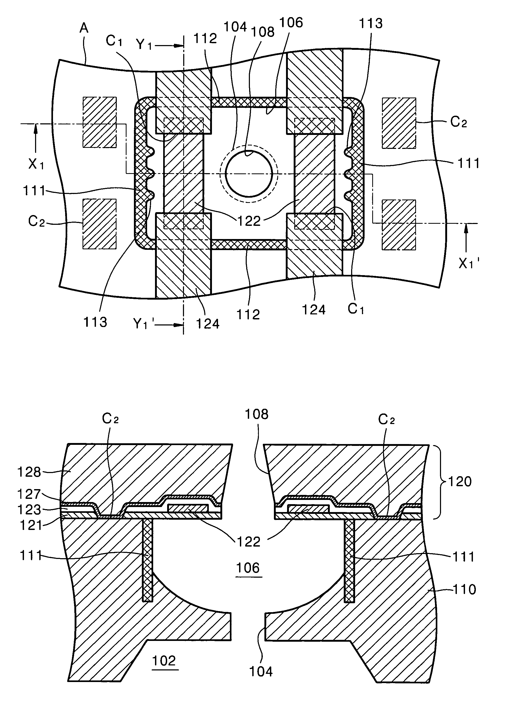
[0065]In the present invention, inner surfaces of the first sidewalls 111 are uneven. Specifically, each of the first sidewalls 111 has at least one, or, more preferably, a plurality of, convex projection 113. As a result, a surface area of the inner surfaces of the first sidewalls 111 adjacent to a bubble formed in the ink chamber 106 increases, so that cavitation points move beyond outer edges of heaters 122 toward the first sidewalls 111. This operation will be subsequently described in further detail.

[0066]The first and second sidewalls 111 and 112 are formed of materials other than a material used to form the substrate 110. This selection is necessary because the ink chamber 106 is formed by isotropically etching the substrate 110 using the first and second sidewalls 111 and 112 as an etch stop. Thus, when the substrate 110 is formed of a silicon wafer, the first and second sidewalls 111 and 112 may be formed of silicon oxide.

[0067]The first and second sidewalls 111 and 112 may...

second embodiment

[0092]FIG. 11 illustrates a plan view of an ink-jet printhead according to the present invention. FIG. 12 illustrates a cross-sectional view of the ink-jet printhead taken along a line X2–X2′ of FIG. 11.

[0093]Referring to FIGS. 11 and 12, the structure of the ink-jet printhead according to the second embodiment of the present invention is substantially the same as the structure of the printhead shown in FIG. 6, except for a shape of a first sidewall 211. Thus, only the shape and function of the first sidewall 211 will be described below.

[0094]The ink chamber 106 is defined by the first sidewall 211 and a second sidewall 212 to have a substantially rectangular shape. A pocket 213 of the ink chamber 106 is formed in each of the first sidewalls 211, which are formed in a widthwise direction of the ink chamber 106. The pocket 213 opens toward a center of the ink chamber 106. Due to the pocket 213, when bubbles formed below the heaters 122 contract and collapse, the resultant cavitation ...

third embodiment

[0107]In the third embodiment, two main heaters 322 are disposed at opposite sides of the nozzle 108 above the ink chamber 106, which is defined by the first sidewalls 111 and the second sidewalls 112. Two auxiliary heaters 323 are disposed between each of the two main heaters 322 and a corresponding one of the first sidewalls 111 adjacent thereto. The main heaters 322 have a substantially rectangular shape having a longer length parallel to the first sidewalls 111. The auxiliary heaters 323 have a substantially rectangular shape and are disposed parallel to the main heaters 322. The main heaters 322 and the auxiliary heaters 323 may be formed of the same material as the material used to form the heaters according to the previously-described embodiments of the present invention.

[0108]One of the main heaters 322 and a corresponding one of the auxiliary heaters 323 are both connected to a conductor 324, so that a current may be simultaneously applied to the main heater 322 and the aux...


PUM


Abstract

A thermally-driven ink-jet printhead includes a substrate having an ink chamber to be filled with ink to be ejected, a manifold for supplying ink, and an ink channel for providing flow communication therebetween. First and second sidewalls are formed to a predetermined depth from an upper surface of the substrate and define the ink chamber to have a substantially rectangular shape. A nozzle plate including a plurality of material layers is formed on the substrate. A nozzle passes through the nozzle plate and is in flow communication with the ink chamber. A heater is disposed between the nozzle and one of the first sidewalls above the ink chamber. A conductor is electrically connected to the heater. The conductor and the heater are disposed within the nozzle plate. A shifting feature moves cavitation points beyond an outer edge of the heater.

Description

BACKGROUND OF THE INVENTION[0001]1. Field of the Invention[0002]The present invention relates to an ink-jet printhead. More particularly, the present invention relates to a thermally-driven ink-jet printhead having an improved structure that is capable of preventing cavitation damage to a heater.[0003]2. Description of the Related Art[0004]In general, ink-jet printheads are devices for printing a predetermined image, color or black, by ejecting a small volume droplet of ink at a desired position on a recording sheet. Ink-jet printheads are generally categorized into two types depending on which ink ejection mechanism is used. A first type is a thermally-driven ink-jet printhead in which a source of heat is employed to form and expand bubbles in ink to cause an ink droplet to be ejected due to the expansive force of the formed bubble. A second type is a piezoelectrically-driven ink-jet printhead, in which an ink droplet is ejected by a pressure applied to the ink and a change in ink ...

Claims


Application Information

Patent Timeline
Patent Type & Authority Patents(United States)
IPC IPC(8): B41J2/05B41J2/14B41J2/16B41J2/335
CPCB41J2/1404B41J2/14056B41J2/1412B41J2/14129B41J2/14137B41J2002/14177B41J2002/1437B41J2202/11B41J2/335
Inventor KUK, KEONSHIN, SEUNG-JOOSOHN, DONG-KEELEE, YONG-SOOOH, YONG-SOOLIM, JI-HYUKBAEK, SEOG-SOONCHOI, MUN-CHEOL
Owner SAMSUNG ELECTRONICS CO LTD
Why Eureka
Try Eureka