Flow regulating valve element and valve seat with same

A flow regulating valve and spool technology, applied in the direction of coolant flow control, multi-way valve, valve device, etc., can solve the problems of branch flow drop, affect heat dissipation capacity, interfere with fluidity, etc., to increase the number of collisions, Avoid cavitation damage and reduce the effect of impact

Active Publication Date: 2019-01-01
ANHUI JIANGHUAI AUTOMOBILE GRP CORP LTD
View PDF6 Cites 1 Cited by
  • Summary
  • Abstract
  • Description
  • Claims
  • Application Information

AI Technical Summary

Problems solved by technology

[0005] The flow valve seat in the prior art has the following problems: after the first branch 10 and the second branch 20 are opened, that is, when they are opposite to the first inlet 401 and the second inlet 402, they enter from the two branches respectively. The cooling liquid in the core 40 directly merges inside the core body 40. The liquids flowing in from the two branches have opposite flow directions, and after the confluence, they will produce a hedge against each other, which will seriously interfere with each other's fluidity, resulting in a decrease in the flow rate of the branches. cooling capacity

Method used


Image

  • Flow regulating valve element and valve seat with same
  • Flow regulating valve element and valve seat with same
  • Flow regulating valve element and valve seat with same

Examples


Embodiment Construction

[0042] The embodiments described below by referring to the figures are exemplary only for explaining the present invention and should not be construed as limiting the present invention.

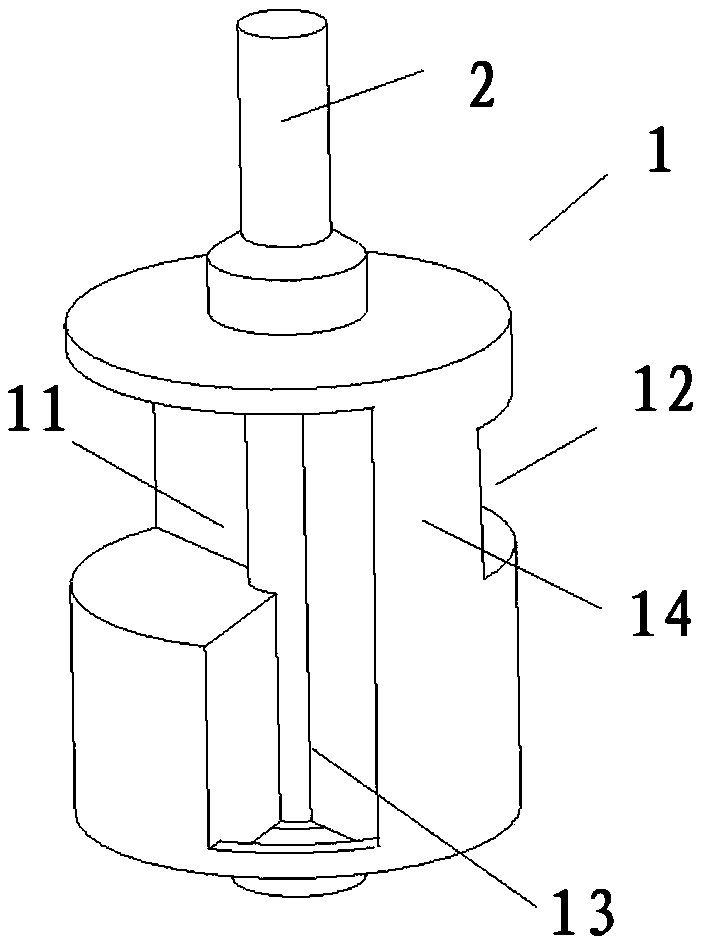
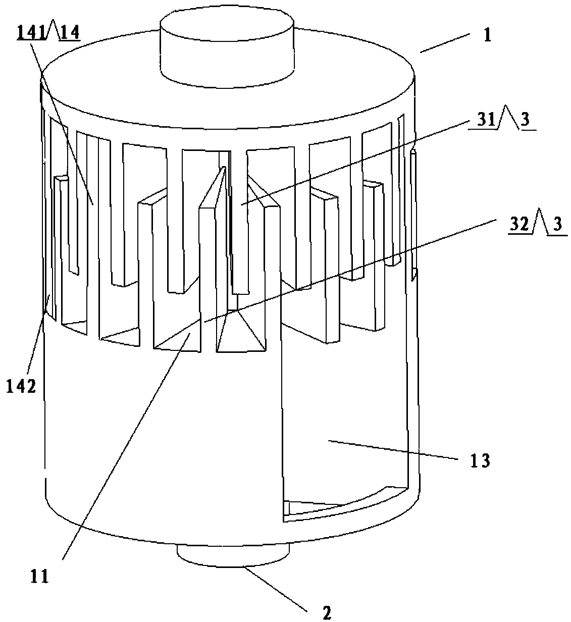
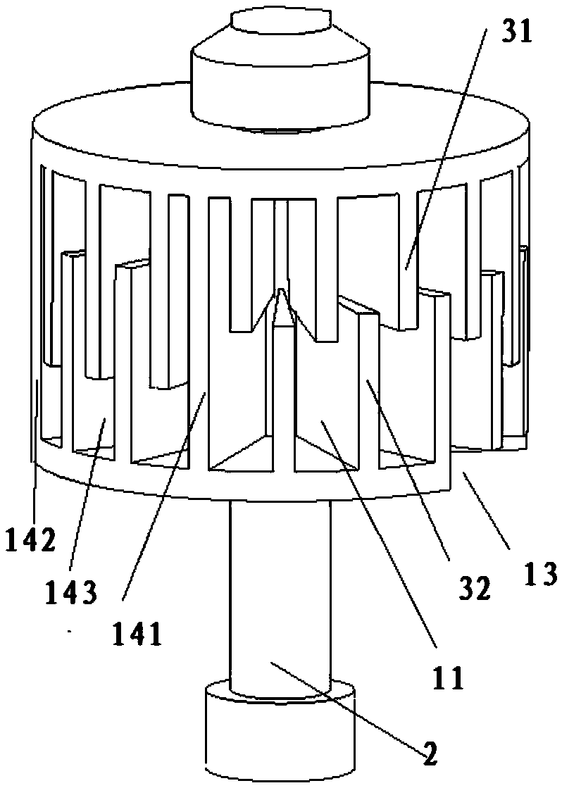
[0043] Such as Figure 1-3 As shown, the present invention discloses a flow regulating valve core, comprising: a valve core body 1 and a rotating shaft 2, the valve core body 1 is fixedly connected to the rotating shaft 2 to rotate synchronously with the rotating shaft 2; the valve The core body 1 has a cylindrical structure, and the central axis of the rotating shaft 2 is coaxial with the central axis of the valve core body 1 .

[0044] The valve core body 1 includes a first liquid inlet channel 11, a second liquid inlet channel 12, a first liquid outlet channel 13, a second liquid outlet channel and a blocking portion 14;

[0045]The first liquid inlet channel 11 communicates with the first liquid outlet channel 13, and the first liquid inlet channel 11 is set to communicate with the first...


PUM


Abstract

The invention discloses a flow regulating valve element and a valve seat with the same. The flow regulating valve element comprises a valve element body and a rotating shaft, wherein the valve elementbody is fixedly connected with the rotating shaft to rotate synchronously with the rotating shaft. The valve element body comprises a first liquid inlet passage, a second liquid inlet passage, a first liquid outlet passage, a second liquid outlet passage and a plugging portion. The first liquid inlet passage is in communication with the first liquid outlet passage, and the first liquid inlet passage is arranged to be in communication with a first liquid inlet pipe of the valve seat. The second liquid inlet passage is in communication with the second liquid outlet passage, and the second liquid inlet passage is arranged to communicate with a second liquid inlet pipe of the valve seat. The first liquid outlet passage and the second liquid outlet passage are arranged to communicate with a valve seat outlet pipe. The first liquid inlet passage and the second liquid inlet passage are separated by the plugging portion. Compared with the prior art, the hedging collision of liquid of two branches is avoided by arranging the two independent liquid inlet passages and the two independent liquid outlet passages in the valve element, so that the flow drop caused by hedging is avoided, and theimpact on heat dissipation capability is reduced.

Description

technical field [0001] The invention relates to the technical field of valve bodies, in particular to a flow regulating valve core for an engine cooling system and a valve seat with the valve core. Background technique [0002] The function of the engine cooling system is to dissipate part of the heat generated by the engine in time to ensure that the engine works at the most suitable temperature. Because only when the engine water temperature is within a reasonable range, the engine can run normally and maintain normal power and torque output. [0003] Under normal circumstances, the control of the engine water temperature is realized by adjusting the coolant flow rate of the cooling system. High coolant flow, strong heat dissipation, lower engine water temperature; low coolant flow, poor heat dissipation, engine water temperature rise. At present, the coolant flow is mainly controlled through the flow regulating valve seat. Usually, each branch is converging at the inlet...

Claims


Application Information

Patent Timeline
Patent Type & Authority Applications(China)
IPC IPC(8): F16K11/02F01P7/14
CPCF01P7/14F01P2007/146F16K11/02
Inventor 刘吉林王军姚炜王宏大王次安张超卓丽颖赵真真
Owner ANHUI JIANGHUAI AUTOMOBILE GRP CORP LTD
Why Eureka
Try Eureka