Shaft rotational flow and energy dissipation tunnel spillway with diving spinning pier

A technology of flood discharge tunnel and swivel pier, which can be used in water conservancy projects, marine engineering, coastline protection and other directions, and can solve problems such as reduction of water flow energy in shafts

Active Publication Date: 2020-10-30
洛阳水利勘测设计有限责任公司
View PDF8 Cites 1 Cited by
  • Summary
  • Abstract
  • Description
  • Claims
  • Application Information

AI Technical Summary

Problems solved by technology

However, in the current vertical shaft swirling flow energy dissipation flood tunnel engineering structure, with the upgrading of the scale of the project, the wall of the flood discharge tunnel (such as the wall of the vertical shaft and the wall of the flat tunnel) often has the phenomenon of water flow separation and generates a large negative pressure. Only through the existing techn

Method used


Image

  • Shaft rotational flow and energy dissipation tunnel spillway with diving spinning pier
  • Shaft rotational flow and energy dissipation tunnel spillway with diving spinning pier
  • Shaft rotational flow and energy dissipation tunnel spillway with diving spinning pier

Examples


Example Embodiment

[0018] Example 1:

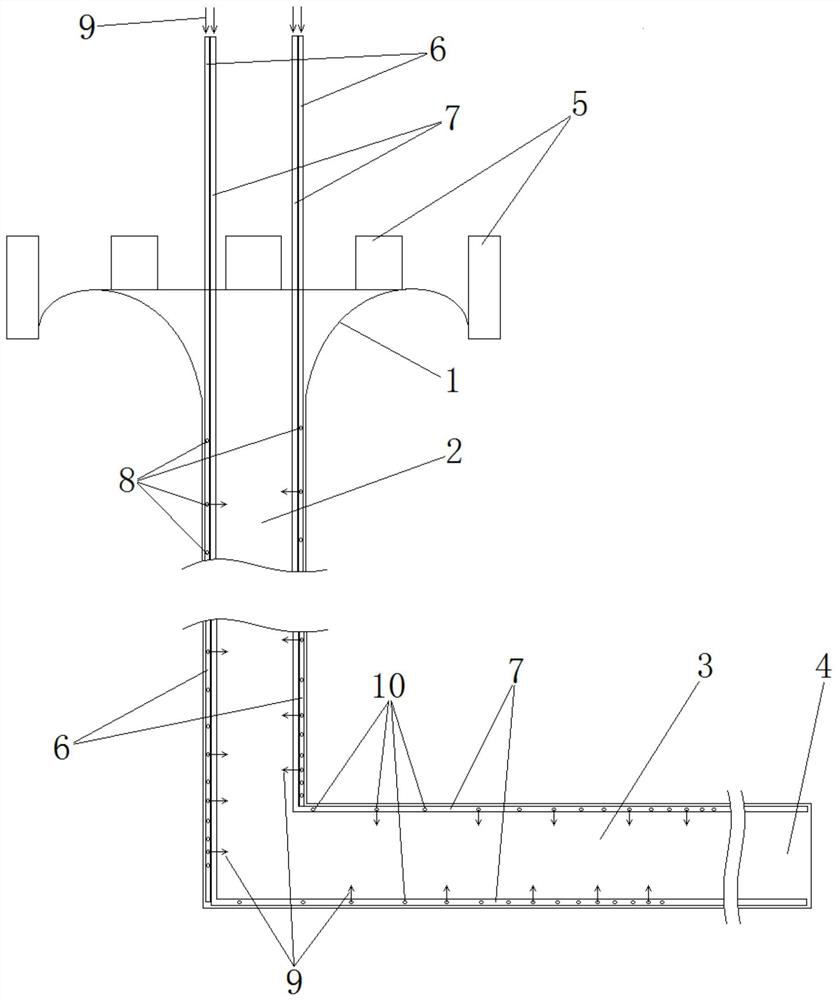
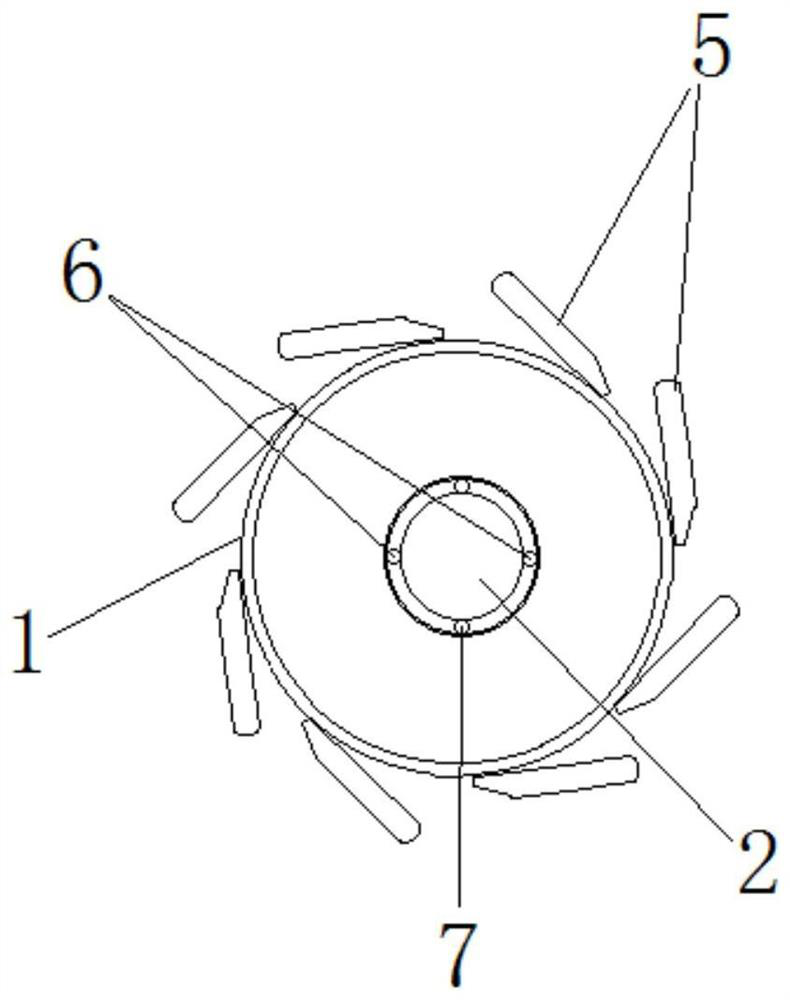
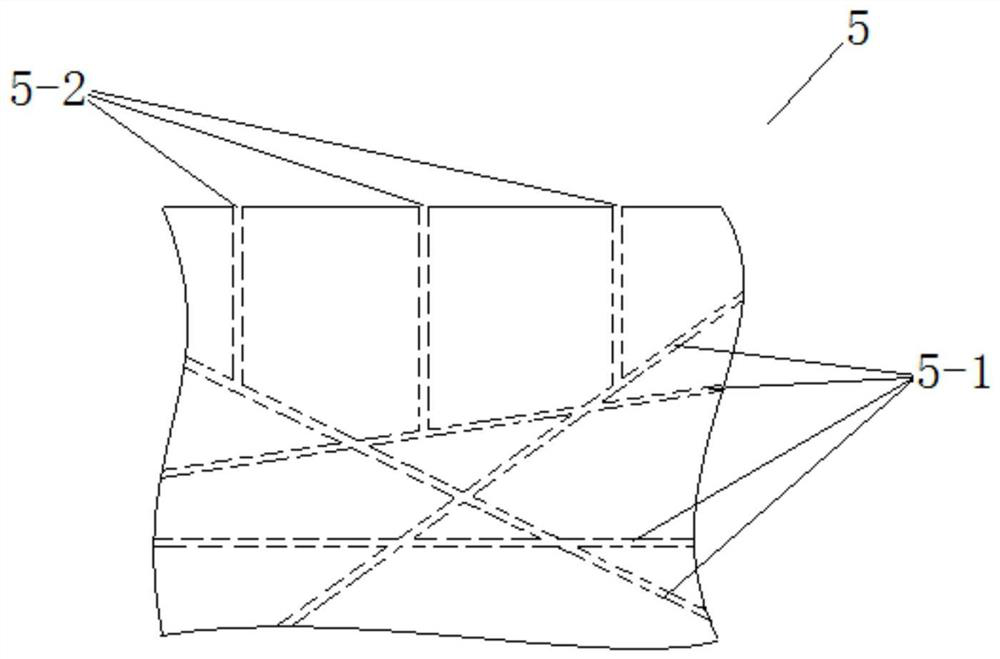
[0019] See figure 1 with figure 2 , The embodiment of the present invention provides a diving pier shaft swirling energy dissipation flood discharge tunnel, including a water inlet, an annular weir 1 is provided on the outer circumference of the water inlet, and a plurality of piers 5 are provided on the outer periphery of the annular weir 1. The water inlet is connected to the shaft 2, the shaft 2 is connected to the flat hole 3, and the flat hole 3 is connected to the water outlet 4, and further includes a plurality of shaft supplementary pipes 6 and a plurality of flat hole supplementary pipes 7; wherein the plurality of vertical shaft supplementary pipes 6 are used for the vertical shaft 2 is supplemented with air 9 at the wall of the well, each vertical well air supply pipe 6 is evenly arranged along the circumference of the shaft wall of the shaft 2 and fixed on the well wall, and the air inlet at the upper end of each vertical well air supply pipe 6 is ...

Example Embodiment

[0020] Example 2:

[0021] On the basis of Example 1, the number of openings of the first air outlet holes 8 along the longitudinal direction of each vertical well supplementary pipe 6 gradually increases from top to bottom, because the air flow in the vertical well supplementary pipe 6 will gradually increase from top to bottom. The first air outlet 8 is discharged, so the airflow will gradually decrease. Therefore, the airflow output is equalized by gradually increasing the number of openings along the vertical shaft supplementary pipe 6 from top to bottom, so that the entire shaft wall The upper can uniformly output the air flow introduced from the outside, so that the pressure on the entire shaft wall is even, and it is also conducive to better mixing the outside air into the water flow, so as to achieve the effect of uniform energy dissipation; The part of the air supply pipe 7 located in the flat hole 3 gradually increases in the number of openings along the longitudinal di...


PUM


Abstract

The invention provides a shaft rotational flow and energy dissipation tunnel spillway with a diving spinning pier. An outer circumference of a water inlet of the tunnel spillway is provided with an annular weir, a plurality of spinning piers are arranged outside the annular weir, the water inlet is connected with a shaft, the shaft is connected with an adit, the adit is connected with a water outlet, the tunnel spillway further comprises a plurality of shaft air supplementary pipes and a plurality of adit air supplementary pipes, the shaft air supplementary pipes are used to supplement air tothe wall of the shaft, an air inlet at the upper end of each shaft air supplementary pipe is higher than the highest water level of a reservoir, and each shaft air supplementary pipe is provided witha plurality of air outlets on the pipe wall of the shaft; the adit air supplementary pipes are used to supplement air to the wall of the adit, the air inlet at the upper end of each adit air supplement pipe is higher than the highest water level of the reservoir, and each adit air supplementary pipe is provided with a plurality of second air outlets on the pipe wall of the audit. The shaft rotational flow and energy dissipation tunnel spillway can use negative pressure generated by the water flow separation phenomenon of the tunnel spillway to introduce outside air so as to reduce the negativepressure and increase the pressure on the wall of the tunnel spillway, and the cavitation damage of the tunnel spillway is prevented.

Description

Technical field [0001] The invention belongs to the technical field of hydraulic structures, and particularly relates to a diving pier shaft swirling flow energy dissipation flood discharge tunnel. Background technique [0002] In the construction of water conservancy and hydropower projects, when the retaining structure of the reservoir is an earth-rock dam, when the topography on both sides of the dam site is steep, the flood discharge tunnel is often used. The principle of swirling energy dissipation is to use the flood discharge flow to rotate in the shaft (or flat cave) channel, which greatly enhances the friction effect between the water flow and the side wall of the channel, and increases the flow, so that the water flows through different flow directions along the way. Blending to achieve the reduction of water flow energy, the prior art shaft swirling energy dissipation flood discharge tunnel uses the swirling structure of the shaft wellhead to convert the horizontal wat...

Claims


Application Information

Patent Timeline
IPC IPC(8): E02B8/06
CPCE02B8/06
Inventor 查斌海彬张修远朱德功霍香丽王治光李明王婷靳润芳寇祖河张艳艳武彬
Owner 洛阳水利勘测设计有限责任公司
Why Eureka
Try Eureka